Later in the tutorial, we will create two measures to track the variation of the gap between the Turnlamp and Headlamp. Those measures will use points. Before we can create the measures, we need to create the points.
•Click ![]() Feature Points to open the Feature Points dialog.
Feature Points to open the Feature Points dialog.
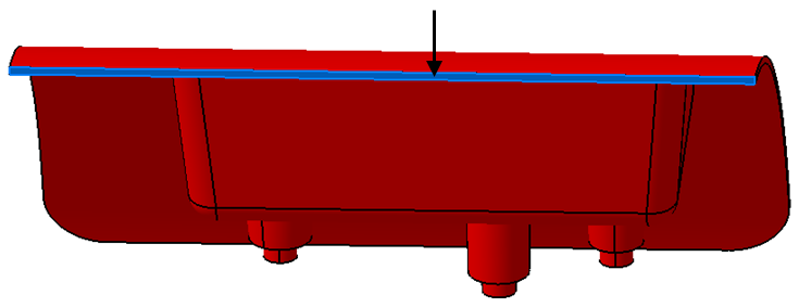
•Click [Feature][Select Feature] then select the Turnlamp surface highlighted in the image below. (Be sure to pick the surface and not a CadEdge).
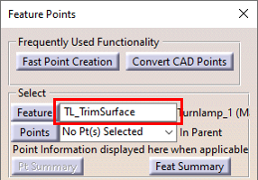
•Change the name of the CadSurf to "TL_TrimSurface" by editing the text in the field next to the [Feature]below the [Del Pts on Feature] button as shown below.
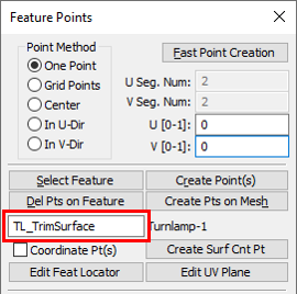
•Select One Point in the Feature Point ParametersPoint Method.
One Point creates a local grid on the selected feature. The location where the point will be created is set by adjusting the U and V coordinates, shown by the arrow in the graphics. The U and V coordinates must be between 0 and 1. An example of how the U and V coordinates controls the point location is shown below.The red "x" is the Feature Locator Point of the selected feature and it represents the feature in point-based moves, tolerances, and measures. The Feature Locator Point is the average of the nodes that makeup the feature.
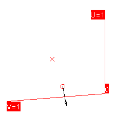
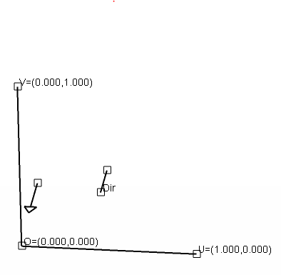
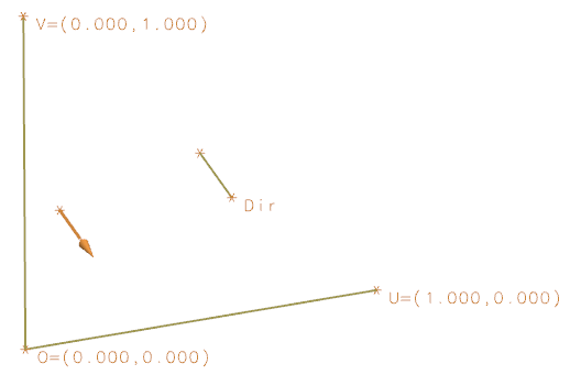
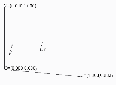
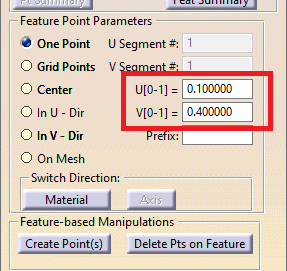
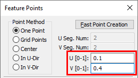
•Adjust the U and V coordinates until the arrow is at the top edge of the TL_TrimSurface. The top is in the +z direction. (Hint: The U and V values shown in the previous picture are just an example and are not the values that should be used for this point).
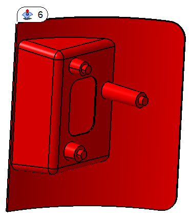
•Click [Create Point(s)]. You should now have a point at the location in the image below.
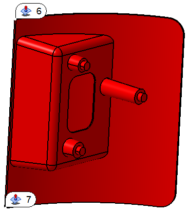
•Adjust the U and V coordinates until the arrow is now at the bottom outboard edge of the TL_TrimSurface. The bottom is in the -z direction.
•Click [Create Point(s)]. You should now have two points at the locations in the image below.
•Click [Close] in the Feature Points dialog.
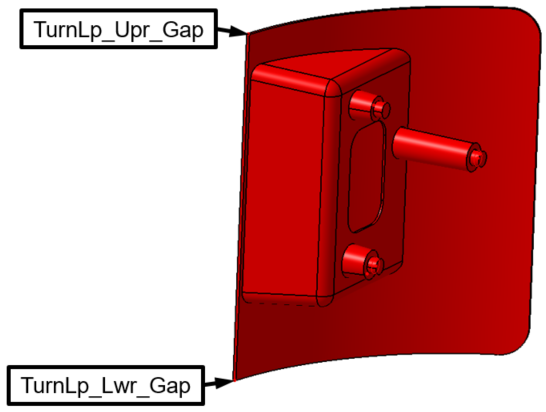
•Use the ![]() Points button to open the Points dialog and rename the points to "TurnLp_Upr_Gap" and "TurnLp_Lwr_Gap" as shown in the image below.
Points button to open the Points dialog and rename the points to "TurnLp_Upr_Gap" and "TurnLp_Lwr_Gap" as shown in the image below.
You will now repeat these steps to create measurement points on the corresponding surface of the Headlamp.
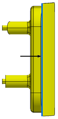
•Create an upper point and a lower point on the surface highlighted below.
•Rename the feature "HL_TrimSurface".
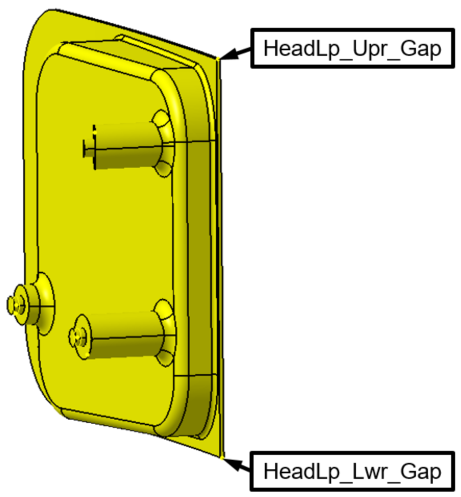
•Rename the points "HeadLp_Upr_Gap" and "HeadLp_Lwr_Gap".
You should now have two points on the Headlamp similar to the image below.
•From File, select Save Management.
•Highlight the Lesson3.CATProduct file and click [Save].
•Click [OK] in the Save Management dialog. The model is not actually saved until you click OK.
•Highlight the ![]() Share icon and select Save in the drop-down list to save the Simulation.
Share icon and select Save in the drop-down list to save the Simulation.
•![]() Save the model.
Save the model.
•Save the model.