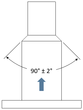
An ![]() Angle Size GD&T is used to vary the angle size as it may be seen on the drawing. It can be used to vary the angle size of a single tapered feature or the angle size between two different features.
Angle Size GD&T is used to vary the angle size as it may be seen on the drawing. It can be used to vary the angle size of a single tapered feature or the angle size between two different features.

Creating Angle Size Procedure:
1.In the GD&Ts dialog, select ![]() Angle Size in the drop-down list and select [Add GD&T]. This will open up the GD&T dialog.
Angle Size in the drop-down list and select [Add GD&T]. This will open up the GD&T dialog.
2.Underneath the Features list, select [Add].
3.Select the feature(s) that are involved in the dimension.
4.Click [OK][Close] in the Pick FeatureSelect dialog
At this point the GD&T dialog will pop back up. Notice that the features selected are now in the Features list in the top half of the dialog with the first picked feature defaulted as the Origin. Reverse the selection order to swap the origin feature.
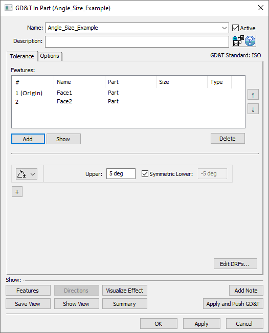
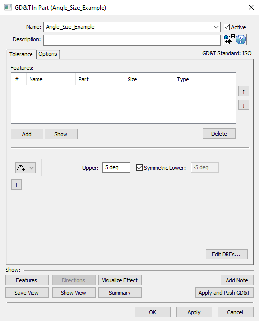
5.In the Upper and Lower fields, enter the range for the GD&T. Note: if the tolerance is not symmetric, then the Symmetric checkbox must be deactivated to enable the Lower text entry field.
5.Select [OK] to exit the dialog and the save the GD&T.
How this GD&T Varies the Feature - Two Features:
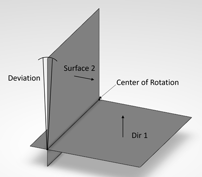
When two features are selected with the  Angle Size GD&T, the second feature will be the only feature that deviates from its nominal location. The center of rotation for the angle will be the intersection between the two features selected. The variation will be around Center of Intersection of Feature 1 and Feature 2. Note: selecting more than two features for the
  Angle Size GD&T is not supported.
A sample feature with how an ![]() Angle Size GD&T would commonly deviate it is shown below.
Angle Size GD&T would commonly deviate it is shown below.
Example Fig.1 |
Example Fig.2 |
|
A side view of two planes selected for the Angle Size GD&T. |
How this GD&T Varies the Feature - Tapered Feature:
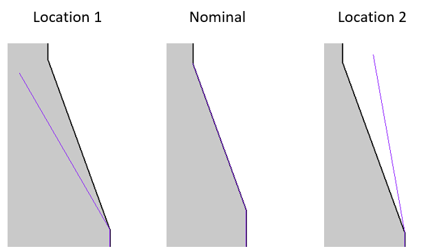
The only supported case for the  Angle Size GD&T that requires only one feature is varying the angle of a tapered feature such as a cone. If this is the case then 3DCS will vary the angle as specified, holding the smaller diameter as the "origin" of the angular variation.
A sample feature with how an ![]() Angle Size GD&T would commonly deviate it is shown below.
Angle Size GD&T would commonly deviate it is shown below.

A side view of a tapered conical feature selected for the Angle Size GD&T.
How this GD&T Varies the Feature - Mixed Feature
Angle GD&T between cylinder and plane uses the cylinder's axis as reference and deviates the plane.
