A ![]() Dimensioning Location GD&T is used to locate a feature (varying feature) relative to another feature (origin feature). The varying feature will vary within a specified range relative to the origin feature which means that any variation on the origin feature from any other GD&Ts will also be seen at the varying feature. The origin feature can be thought of as the Datum for the varying feature. The
Dimensioning Location GD&T is used to locate a feature (varying feature) relative to another feature (origin feature). The varying feature will vary within a specified range relative to the origin feature which means that any variation on the origin feature from any other GD&Ts will also be seen at the varying feature. The origin feature can be thought of as the Datum for the varying feature. The ![]() Dimensioning Location GD&T is used for any standard linear dimension tolerances that may be found on a drawing. A few examples of these tolerances are shown below.
Dimensioning Location GD&T is used for any standard linear dimension tolerances that may be found on a drawing. A few examples of these tolerances are shown below.
Note: To not choose the origin and varying feature but rather have them change size symmetrically relative to a mid-plane, a ![]() Size GD&T cam be used if the two features are selected and no
Size GD&T cam be used if the two features are selected and no ![]() or S
or S![]() is used in the Zone Shape input drop-down.
is used in the Zone Shape input drop-down.
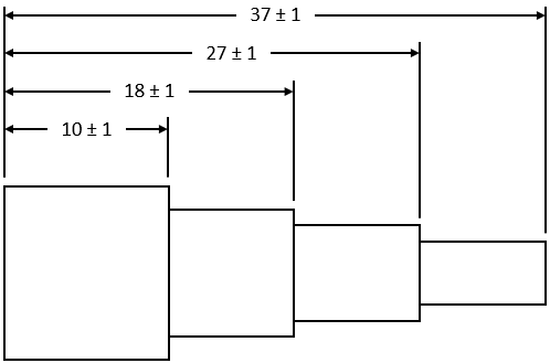
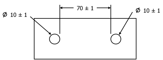
Creating Dimensioning Location Procedure:
1.In the GD&Ts dialog, select ![]() Dimensioning Location in the drop-down list and select [Add GD&T]. This will open up the GD&T dialog.
Dimensioning Location in the drop-down list and select [Add GD&T]. This will open up the GD&T dialog.
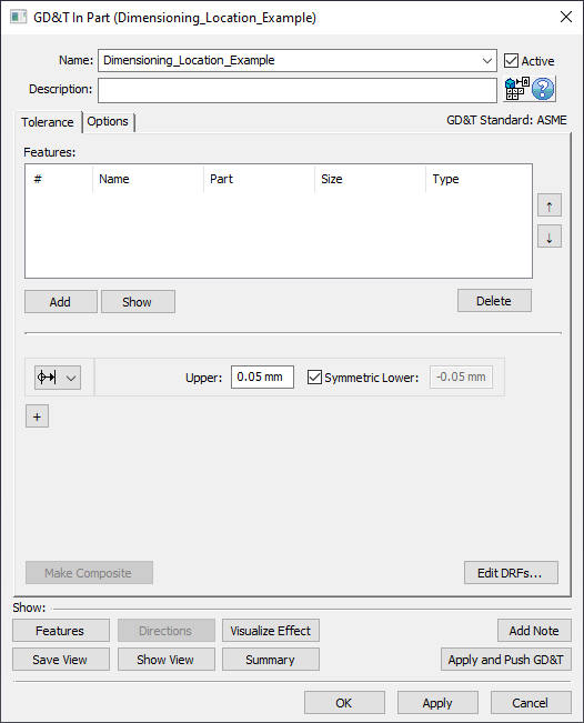
2.Underneath the Features list, select [Add].
3.Select the feature from the model to be used as the Origin Feature.
4.Select the feature from the model to be used as the Varying Feature.
At this point the GD&T dialog will pop back up.
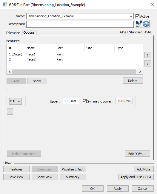
Notice that [Add] is now greyed out. This is because the ![]() Dimensioning Location GD&T only allows two features: an Origin Feature and a Varying Feature. Also notice that there is text mentioning that the first Feature in the list is the origin. If Features are selected in the incorrect order, the up and down arrow buttons on the right of the Features list can be used to correct any mistakes.
Dimensioning Location GD&T only allows two features: an Origin Feature and a Varying Feature. Also notice that there is text mentioning that the first Feature in the list is the origin. If Features are selected in the incorrect order, the up and down arrow buttons on the right of the Features list can be used to correct any mistakes.
5.Select [OK] to exit the dialog and the save the GD&T.
Examples of Dimensioning Location Uses:
1.Chain Dimensioning
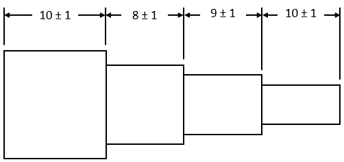
In the case of Chain Dimensioning, it will take four different ![]() Dimensioning Location GD&T inputs and it would be recommended (but not mandatory) to work either left-to-right (or right-to-left) such that for each of the four GD&T inputs, the left (or right) of the two faces will be the Origin Feature. This will maintain the relationships for each segment while also getting the correct variation if a measure was made between any two faces.
Dimensioning Location GD&T inputs and it would be recommended (but not mandatory) to work either left-to-right (or right-to-left) such that for each of the four GD&T inputs, the left (or right) of the two faces will be the Origin Feature. This will maintain the relationships for each segment while also getting the correct variation if a measure was made between any two faces.
2.Base Dimensioning

In the case of Base Dimensioning, it will also take four different ![]() Dimensioning Location GD&T inputs and it would be recommended to treat the "base" face (the left-most face in this example) as the Origin Feature in each of the four GD&T inputs. This will maintain the relationships for each length back to the "base" face while also getting the correct variation if a measure was made between any two faces.
Dimensioning Location GD&T inputs and it would be recommended to treat the "base" face (the left-most face in this example) as the Origin Feature in each of the four GD&T inputs. This will maintain the relationships for each length back to the "base" face while also getting the correct variation if a measure was made between any two faces.
3.Direct Dimensioning
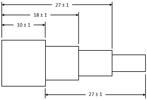
In the case of Direct Dimensioning, it will ahain take four different ![]() Dimensioning Location GD&T inputs and it would be recommended to treat the "base" face (the left-most face in this example) as the Origin Feature in three of the four GD&T inputs. The final input will be the bottom dimension (the Direct Dimension of this example) which will have the left face as the Origin Feature and the far right face as the Varying Feature.
Dimensioning Location GD&T inputs and it would be recommended to treat the "base" face (the left-most face in this example) as the Origin Feature in three of the four GD&T inputs. The final input will be the bottom dimension (the Direct Dimension of this example) which will have the left face as the Origin Feature and the far right face as the Varying Feature.
Using Custom Directions Between Features of Size:
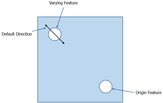
When dimensioning between two features of size, such as two holes for example, 3DCS will by default assume variation is meant to be along the vector direction between the two features. When looking at the example below, the lower-right hole is the Origin Feature and the other hole is the Varying Feature. The displayed direction is the default direction that 3DCS will vary the Varying Feature along.
However, it is possible that on the drawing the control dimension that is being simulated actually looks like the image below.
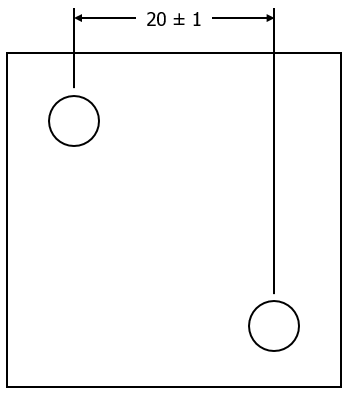
If this is the case then the user must set a Custom Direction in the Options tab of the GD&T dialog by activating the Use custom direction option and either typing in an i, j, and k value or using the [Set Direction] option to set the direction using a different method within 3DCS. (See Vector Direction)
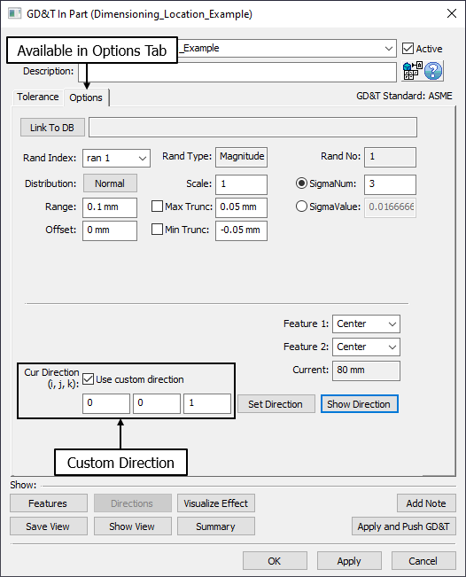
Note: the direction is based off of the Local Coordinate System for the part or assembly the GD&T was created in rather than the Global Coordinate System typically displayed in the CAD software for the assembly file that is currently displayed. Use [Show Direction] to verify the direction selected matched expectation.
Dimensioning to the Edges of Features of Size:
When one or more Feature of Size is used in a  Dimensioning Location GD&T, it is possible that the dimension is not meant to maintain between centers of holes, but rather control the distance between the inner or other edges of the holes. One possible example of this is shown in the image below.

This means that any change in the size of either hole should not effect the distance between the holes edges. To create this dimension in 3DCS, there is a Center, Min, and Max option for Features of Size in the Options tab. There is also a Current value displayed to help users be sure the dimension they are creating lines up with what they see on the drawing. 3DCS will always default these options to Center, but for the example above, Feature 1 and Feature 2 should both be set to Min.
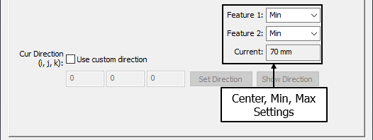
Note: While the Current value will update based on the Center, Min, Max setting, it will not update based on any Custom Direction used in the dialog.
The Min Max and Center setting can also be extracted on extracting Dimensioning Location GD&T from the Parts.
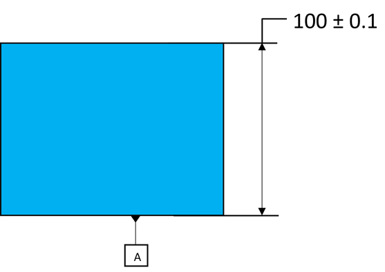
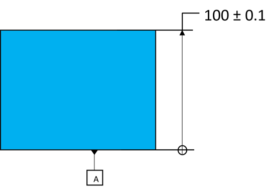
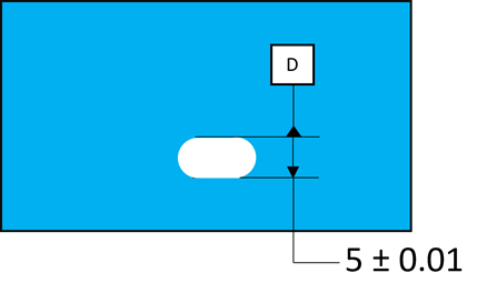
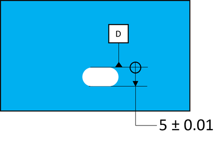
Dimensioning Location cases: The Dimensioning Location GD&T can be defined in the PMI several ways, but depending on how a Datum Feature and a Size Tolerance are defined and then extracted, this could generate a Dimensioning Location.
|
|
If a Size Tolerance existed on a feature with a Datum, this would result in creating a Dimensioning Location, with the Origin feature on the Datum Feature. |
|
|
|
In this case, one of the features on this slot is a Datum Feature. If this was extracted into 3DCS, users will notice Datum D will be one of the surfaces and then a Dimensioning Location will be created. Make sure the Datum is defined on the two features to correctly extract as a Size Tolerance. |
|
