In some manufacturing situations, flexible parts are bent during assembly. This routine is used to simulate the bending of parts during the assembly process. In 3DCS, bending is performed by using a move to locate points on one side of a bend plane. Most move types can be used as bend moves.
|
See Also:Example model:C:\Users\Public\Documents\DCS\3DCS_V5_8_2_0_0\3DCS CAD & Example Models\Reference Models\Moves\Routine - Three Point Move\Bend Option\Bend_Option_Example.wtx |
Procedure:
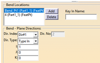
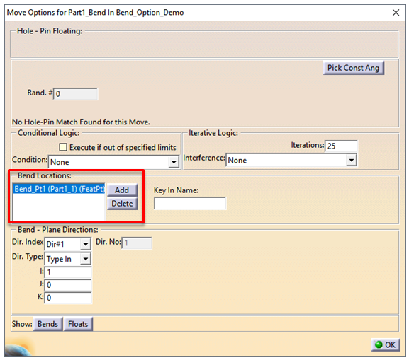
•Create a new move for the flexible feature of the part. Click on the Options button in the Move dialog box. A new dialog box will come up.
•Click on Add OR Key In Point Name to select the points. Click Delete if you wish to remove points.
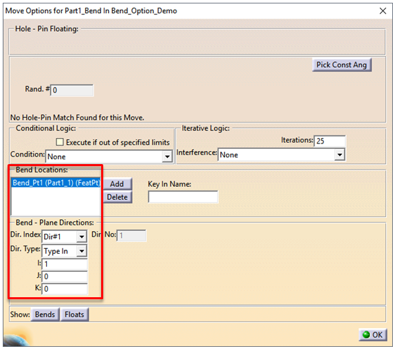
•Highlight one point in the Bend Locations dialog box and chose the Dir. Type for it. For each point a separate Dir. Index will be automatically selected.
•The Dir. No shows the number of directions.
Example #1:
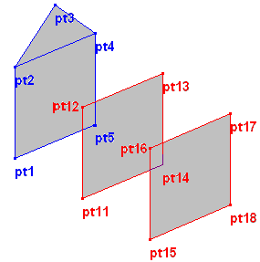
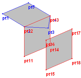
Create the following points at the designated location:
| Part1 | Part2 |
| pt1 1,1,1 | pt11 3,1,1 pt16 5,1,3 |
| pt2 1,1,3 | pt12 3,1,3 pt17 5,3,3 |
| pt3 1,2,4 | pt13 3,3,3 pt18 5,3,1 |
| pt4 1,3,3 | pt14 3,3,1 |
| pt5 1,3,1 | pt15 5,1,1 |
Connect the points as shown below using Edit ![]() Create
Create ![]() Lines.
Lines.
Step 1 : Create a three point move called MOVE1 with object points at pt1, pt2 and pt5 and target points as pt11, pt12 and pt14. Be sure to select Part1 in the Move Objects box.
Step 2 : Create another three point move called MOVE2 with object points at pt2, pt4 and pt3 and target points as pt12, pt13 and pt17.
Step 3 : Click on Options, select Bend Locations and Add pt2 . Set the vector direction as (0,0,1). Close the Options dialog box. Close the Move dialog box.
Step 4 : Animate. You will see that Part1 moves to the object pts in part Part2 for the first move and for the second move the top triangle part bends at the pt2. For this second move, pt3 is moving towards pt17.
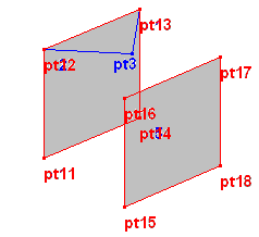
| Step 5 : | Now to see the difference, modify Move2. In the Options dialog box cancel the Bend Condition. Close all dialog boxes and animate again. Notice that the part doesn't bend at pt2, instead it rotates along the line. |
Example #2:
•Start by creating an initial move. This is a standard move without any bends. This will move the part as a whole.
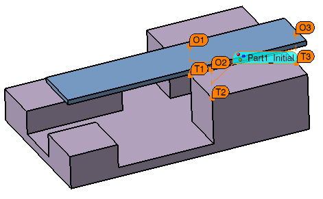
•Create another move that will be used to bend the part. In this example, O1 and T1 are the same point and O2 and T2 are the same point. When there are deviations with the initial move, O1 and T1 will always be coincident and O2 and T2 will always be coincident. Because this is a Three Point Move, O1 and O2 are creating an axis about which O3 will bend to T3.
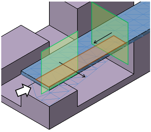
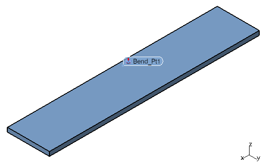
•In the Move Options, add a point to the Bend Locations to turn this into a bend move. A bend move will only move a portion of the part. The location of the bend point determines which portion of the part will move.
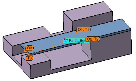
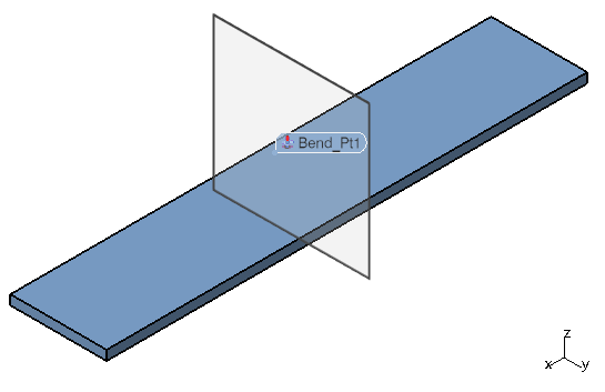
•Enter a direction in the Bend - Plane Directions. A plane is created through the bend point normal to the direction entered.
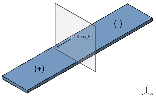
Only points and features on the positive side of the plane (the side the direction points toward) will move. Note that (1,0,0) was entered for the bend direction. This means points and features in the +x direction of the plane will move. If (-1,0,0) were entered as the bend direction, it would be the opposite and only points and features in the -x direction of the plane would move.
3DCS does not bend the CAD part but will bend the mesh and points when the model is built.
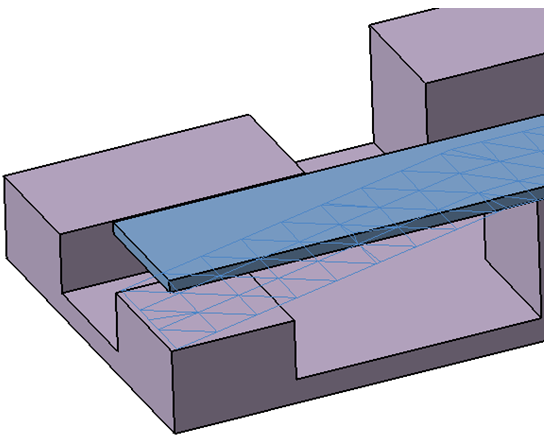
You can add multiple points to the Bend Locations to define multiple planes. Only points and features that are in the positive areas of all planes will move. This is shown by the orange area in the image below. The white arrow is pointing to a mesh line that crosses one of the bend planes. Note how the mesh behaves on either side of the bend plane.