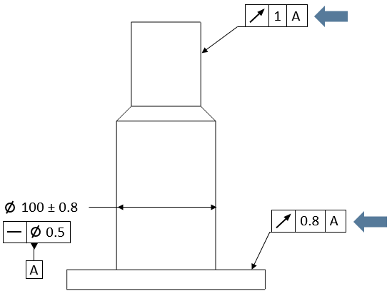
A ![]() Circular Runout GD&T is typically used to vary the location of a cylindrical Feature of Size such as a hole or pin, or vary the form of a planar surface relative to an axial DRF.
Circular Runout GD&T is typically used to vary the location of a cylindrical Feature of Size such as a hole or pin, or vary the form of a planar surface relative to an axial DRF.
Creating Circular Runout Procedure:
1.In the GD&Ts dialog, select ![]() Circular Runout in the drop-down list and select [Add GD&T]. This will open up the GD&T dialog.
Circular Runout in the drop-down list and select [Add GD&T]. This will open up the GD&T dialog.
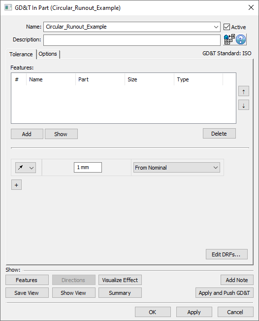
2.Underneath the Features list, select [Add].
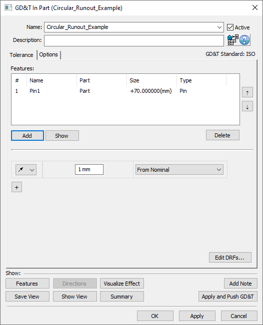
3.Select the feature(s) whose location or form should be varied by this GD&T.
4.Click [OK][Close] in the Pick FeatureSelect dialog
At this point the GD&T dialog will pop back up. Notice that the features selected are now in the Features list in the top half of the dialog.
5.Enter the range in the text entry field.
6.Select a DRF or From Nominal from the Datum Reference Frame drop-down. See Datum Reference Frames for more information about creating and using DRFs.
7.Select [OK] to exit the dialog and the save the GD&T.
How this GD&T Varies the Feature - Diametrical Feature:
In accordance with ASME or ISO standards, unlike with other GD&Ts within 3DCS the type of deviation for a ![]() Circular Runout GD&T is determined by the feature(s) selected and not be inputting a specific zone shape. For a diametrical feature in the Features list, the
Circular Runout GD&T is determined by the feature(s) selected and not be inputting a specific zone shape. For a diametrical feature in the Features list, the ![]() Circular Runout GD&T varies the location of the diametrical feature.
Circular Runout GD&T varies the location of the diametrical feature.
A sample diametrical feature with how a ![]() Circular Runout GD&T would commonly deviate it is shown below.
Circular Runout GD&T would commonly deviate it is shown below.
Note: While only a few deviated locations are shown below, the actual variations will use the entire specified zone.
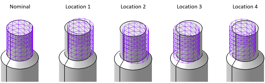
An isometric view of a pin with a Circular Runout GD&T.
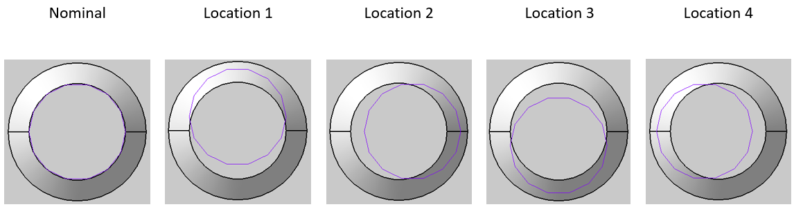
A top view of the same pin with a Circular Runout GD&T.
How this GD&T Varies the Feature - Planar Feature:
A ![]() Circular Runout GD&T when applied to a planar feature will instead deviate the form of the feature. When deviating form, each node on the feature will deviate independently of all other nodes on the surface.
Circular Runout GD&T when applied to a planar feature will instead deviate the form of the feature. When deviating form, each node on the feature will deviate independently of all other nodes on the surface.
A sample planar feature with how a ![]() Circular Runout GD&T would commonly deviate it is shown below.
Circular Runout GD&T would commonly deviate it is shown below.
Note: While only a single deviated feature is shown below, the actual variations will use the entire specified zone.
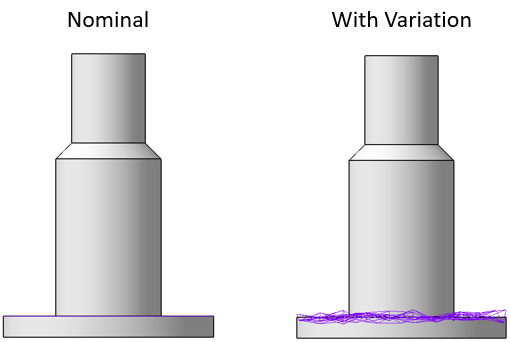
A planar feature with a Circular Runout GD&T applied to it.
A ![]() Circular Runout GD&T will only work with axial or planar features.
Circular Runout GD&T will only work with axial or planar features.