Topics within this section:How to create Point-Based Feature Best Practices |
Procedure:
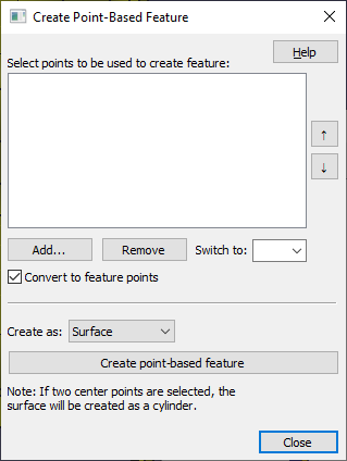
1.Select the ![]() Point-Based Feature.
Point-Based Feature.
2.Select [Add...].
a.Using Convert to Feature Points will be make the Points to a Feature Point, if they are Coordinate Points.
3.Specify Surface or Edge.
4.Select the [Create point-based feature] button.
Commands
[Add Point] to add points to the Point List.
[Remove Point] to remove the highlighted point(s) from the Point List. Select [Remove All] to clear the Point List.
Switch To: Changes the order of the selected point.
[Convert to Feature Points] option will create an association between the new feature and the points in the Point List. In doing so, the Coordinate Points in the Point List will become Feature Points.
As CadSurf: Creates a new CadSurf from the selected points. Requires 3 or more points to create a CadSurf.
As CadEdge Open: Creates a new CadEdge from the selected points. Requires 2 or more points to create a CadEdge.
As CadEdge Closed: Creates the CadEdges and connects the first and last point to close it.
Notes: In the Navigation Tree, double-clicking a surface or right-clicking and choosing Feature Info opens the Surface Info dialog. The Surface Info dialog shows the points associated as a group with the surface in the Entity List. |
Best Practices: Creating Planar Features
Requirements:
•Three or more Coordinate Points. The surface will define an average direction of all the points.
•Points must of in the same direction as surface.
1.Create the points needed to create a planar feature. The Points must use the same direction as the surface.
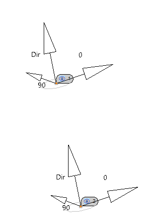
Point-Based Feature Directions requirements |
|
|
|
Correct method to creating Point-Based features |
Incorrect method to creating Point-Based features. |


2.Select ![]() Point -Based Features on the 3DCS Model Creation Toolbar to bring up the Point-Based Feature dialog.
Point -Based Features on the 3DCS Model Creation Toolbar to bring up the Point-Based Feature dialog.
3.Select [Add Point] to add points to the Point List.
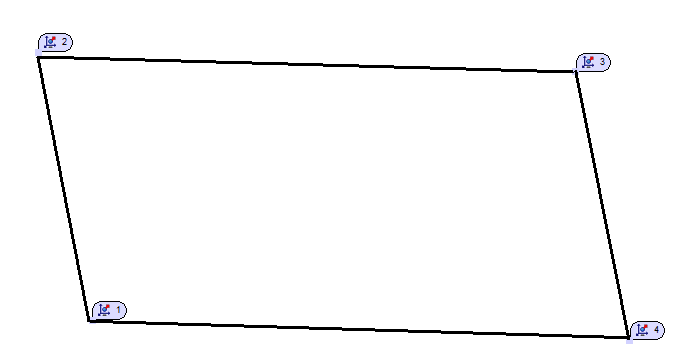
4.Select the Points from the list will highlight them in the graphics. Example: Pick points shown from image above: Pt1, Pt2, Pt3, Pt4.
5.Make sure the setting is set to Create As: Surface.
6.The Convert to Feature Points option will create an association between the new feature and the points in the Point List. In doing so, the Coordinate Points in the Point List will become Feature Points.
7.Select [Add Group] to create the new feature. An outline of the new feature will appear as a mesh in the part.
Procedure: Cylindrical Features
Requirements:
•Two Coordinate Points with Circle Size Tolerances. The size tolerance will define the cylinder size and feature type.
1.Select ![]() Point -Based Features on the 3DCS Model Creation Toolbar to bring up the Point-Based Feature dialog.
Point -Based Features on the 3DCS Model Creation Toolbar to bring up the Point-Based Feature dialog.
2.Select [Add Point] to add points to the Point List.
3.Select the points from the Model Navigator or graphics. Example: Pick points shown from image above: Pt1 and Pt2. The order of the points selected will define the axis direction.
4.Activate the Convert to Feature Points option to create an association between the new feature and the points in the Point List. In doing so, the Coordinate Points in the Point List will become Feature Points and the size tolerances will be deleted.
5.Make sure the setting is set to Create As: Surface.
6.Select [Create point-based feature] to create the new feature.
Notes:•A cylindrical feature will be created, no mesh or surface will be shown in the graphics. •A conical feature can be created by defining two different sizes of size tolerances. •To edit the size or the points, the user can delete the Point-Based feature in the tree and re-define the parameters. |
Procedure: Edge - Open or Closed
Requirements:
•Two or more Coordinate Points.
1.Select ![]() Point -Based Features on the 3DCS Model Creation Toolbar to bring up the Point-Based Feature dialog.
Point -Based Features on the 3DCS Model Creation Toolbar to bring up the Point-Based Feature dialog.
2.Select [Add Point] to add points to the Point List.
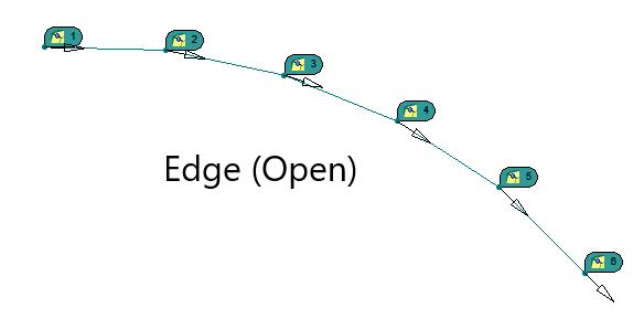
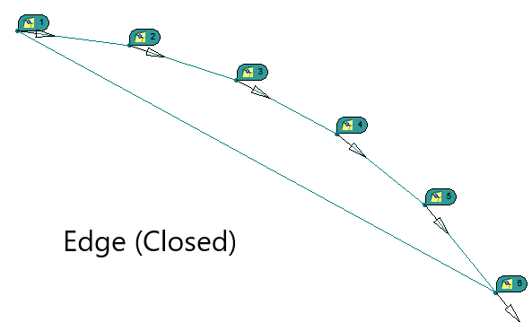
3.Select the points from the Model Navigator or graphics. Example: Pick points shown from image above: Pt1, Pt2, Pt3, Pt4, Pt5, Pt6. The order of the points selected will define the axis direction.
4.Activate the Convert to Feature Points option to create an association between the new feature and the points in the Point List. In doing so, the Coordinate Points in the Point List will become Feature Points.
5.Make sure the setting is set to Create As: Edge (Open) or Edge (Closed).
6.Select [Create point-based feature] to create the new feature.
7.Specify a name for the new feature or click OK to create with a default name.
Notes:As CadEdge Open: Creates a new CadEdge from the selected points. CadEdge Open will be more commonly used in most Move, Tolerance and Measure cases. As CadEdge Closed: Creates the CadEdges and connects the first and last points to close it. CadEdge Closed is designed for Mechanical users that need to loop or track a curve in a Kinematic move. Works best with Contact Constraint. |