The
Users can edit the direction by using Two Point, Normal, Pick Point Direction, and Type-In. When editing the direction, 3DCS will calculate a Right-Hand rule direction.
|
Pick Part: Allows the user to pick a different part to edit an Edge direction. Show Direction: Shows the direction that is applied or a preview of the edited direction. Activate: To use an edited direction. Deactivate will use the default direction. OK: Applies the edge direction and closes the dialog Apply: Applies the new direction. Cancel: Doesn't apply any changes and Closes the dialog .
|
|---|
![]() Default Edge Directions (Line)
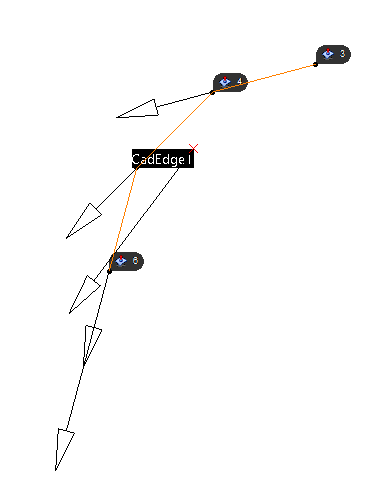
Default Edge Directions (Line)
The direction of an edge will be automatically generated when the user selects on an edge. The direction will be based on the two end points. •Any new Feature Points created on an edge will have the same direction applied to that Feature Point. •GD&T that are applied to an edge will deviate the points and the edge based on the Edge Direction.
|
|---|
Similar to an linear edge feature, a direction of a radial edge will be automatically generated when the user selects on an edge. The direction will be based on the series of points on the curve. A Feature Locator point will be generated, using the average of the total points on the arc. The direction of the Feature Locator will also be an average of all of the Point's directions. •Any new Feature Points created on an edge will have the same direction applied to that Feature Point. •Users can take advantage of changing the Mesh Density to update the Mesh Density from the Preferences dialog. This will create more segments of points on the curve or arc. •GD&T that are applied to an edge will deviate the points and the edge based on the Edge Direction.
|
|---|
![]() Default direction for Circle edges
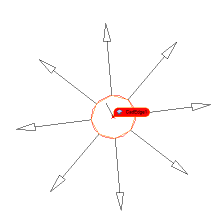
Default direction for Circle edges
When selecting a circle to define a direction, the circle (defined as a Pin or Hole) will have a direction from the Center of the circle, normal the circle's edge. •Edges that are defined as a Hole or a Pin will not be editable to change the edge direction, but will be shown in the list. Selecting the edge in the list will show the edge direction. •Users can use Cylindrical Threshold to modify the circle edge and change to a non-Feature of Size. •Multi-CAD users will need to remove the Feature of Size type from the edge by going to the Feature Point dialog, select Show Features and edit in the Feature Selection dialog.
|
|---|
Notes:•Edges that are defined as a Hole or a Pin will not be able to change the edge direction, but will be able to be seen in the list. Selecting the edge in the list will show the edge direction. (Starting from the center point of the circle and normal of the circle). •The Minimum Segment Number in Preferences can alter the amount of mesh points on the curve, showing more direction vectors on the edge. •Changing the Cylindrical Threshold in 3DCS Preferences curve definition, such as holes or pins.\
|


