The Auto Bend DLL library features moves that handle components and assemblies that are over-constrained on the primary plane. These routines provide several ways to handle over-constraints using some automated rigid-body methods.Alternatively, a user may use the manual bend option in each 3DCS move routine.
|
|
Within this Section:High Point (HighPoint) Random (Random) Auto Bend 2 (dcsMvAutoBend2) Points to High Point (dcsMvPtToHighPts) Morphing CGR From Points Routine 2 (dcsMvInvDistWtMorphyCGR) |
See also...:Autobend: Over-constraining two features (Community)
Example Models:C:\Users\Public\Documents\DCS\3DCS_V5_8_2_0_0\3DCS CAD & Example Models\Reference Models\Moves\AutoBend C:\Users\Public\Documents\DCS\3DCS_V5_8_2_0_0\3DCS CAD & Example Models\Reference Models\Moves\AutoBend_2 |
Locates object on highest primary locators. Use this routine when you want to locate over-constrained object(s) on the highest primary locators. The High Point routine locates an object to the highest three object-target point pairs on the primary plane. Secondary and Tertiary points are treated as in the Six-plane move. The result will be a gap clearance between all primary point pairs as measured along the first Target point direction. No bending or deformation of the part(s) or points is performed with this user routine. ProcessStep 1: The component(s) are initially moved to the target with the first three object-target point pairs. (Internally uses the 3-Point move.) Step 2: The routine internally finds the three highest object-target point pairs among all of the primary point pairs. Step 3: Finally, the object component(s) are positioned with the selected highest point pairs on the primary plane, plus secondary and tertiary planes. (Internally uses the Six-plane move.) InputsThe Object Features list and Target Features list shall have the same number of points; they correlate in Object-Target pairs. 1st to 3rd - Three primary points 4th and 5th - Two secondary points
7th to nth - Additional primary points Direction number ("Dir. No.") must be manually set to equal the number of target points.1st to 3rd - Three vectors for the first three primary target points 4th and 5th - Two vectors for secondary target points
7th to nth - Additional primary points
Move Parts: At least one component should be selected for the Move Parts list.
Notes:Because the first three points are used as the initial primary locators, the move is biased toward these points; especially with a small number of primary points.
|
|---|
![]() Points to High Point (dcsMvPtToHighPts)
Points to High Point (dcsMvPtToHighPts)
This routine transforms an object point/feature to the high point among a set of target points/features. Use this routine when you need to manipulate an individual point or feature surface (not component), and translate it to the high point of a target surface. ProcessStep 1: Measure each target point/node from a common reference location along the given direction vector. Step 2: Identify the target high point by selecting the point/node associated with the most positive measurement from Step 1. Step 3: The first object point (or feature control point) is translated to the selected high point. Other object points/nodes shall be translated the same distance and direction. DescriptionThis routine is used to transform an object point or feature to the high point among a set of target points or features. This move routine manipulates a point or feature independently of a component; no object component need be specified in the Move Parts list. When applied to a feature, the feature's control point will be coplanar/coincident to the high point of the target surface. The high point is defined as the point or node in the most positive location as measured along a direction vector. InputsThe Object Features list contains at least one point or feature to be moved. 1st - One point or feature to be translated to the high point of the target. ... to mth - Other points or features to be translated the same distance and direction.
The Target Features list contains one or more points/features to be evaluated for a high point. 1st to nth - At least one point or feature is required. If a surface feature is selected, each node on the feature is considered for the high point. The Direction list requires one vector used in identifying the high-point. Move Parts: Not required
|
|---|
Locates object on randomized primary locators. Use this routine when you want to locate over-constrained object(s) on any random set of primary locators. The Random routine locates an object to a random set three object-target point pairs on the primary plane. Secondary and Tertiary points are treated as in the Six-plane move. The result will be gap clearances and interferences between all other primary point pairs as measured along the direction vectors. No bending or deformation of the part(s) or points is performed with this user routine. ProcessStep 1: The routine internally and randomly selects three object-target point pairs among all of the primary point pairs. Step 2: The object component(s) are positioned with the randomly selected point pairs on the primary plane, plus secondary and tertiary planes. (Internally uses the Six-plane move.) InputsThe Object Features list and Target Features list shall have the same number of points; they correlate in Object-Target pairs. 1st to 3rd - Three primary point pairs 4th and 5th - Two secondary point pairs
7th to nth - Additional primary point pairs
Direction number ("Dir. No.") must be manually set to equal the number of target points.
One Random Parameter ("Random Param.") must be manually set to determine which of the object-target point pairs shall be selected for the primary locators.
Move Parts: At least one component should be selected for the Move Parts list.
|
|---|
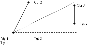
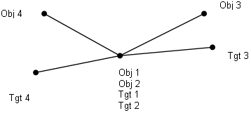
Deforms an over-constrained object to primary locators. Use this routine when you want to first locate the object with something other than a Six-plane move, and when you want to allow automated selection of the bending lines. It is assumed the 3DCS model will initially locate the object(s) to the target before invoking Auto Bend2; more specifically, it is assumed that the first two Object/Target points are located prior to invoking this routine. The Auto Bend2 routine deforms object features to a target. Object triangle patches are bent to the target surfaces defined by the target points and vectors. This routine starts bending with the third object point based on the bending axis specified by the first two object points. After this initial locating scheme, subsequent object points are considered for bending by constructing exclusive bending triangles. The bending action is performed for all entities within object part(s). The bending triangle is identified by projecting target points onto a view plane. Therefore, be careful that the bending point is unique when projected on the view plane. For example, object points spread out across a sphere will not produce unique triangles when projected to a plane -- an invalid case. But a hemisphere would produce unique triangles -- a valid case. The main reason for using this routine is that you can rotate the object part around the line created between the first two object points. ProcessStep 1: The bend operations start with the first triangular patch made of two axis points (O1 and O2), and a bending point (O3). Internally, a section plane is defined at the O1-O2 line and the view direction vector D1. The object point O3, and other object features bounded by the section plane, are rotated about the axis defined by the 1st and 2nd object points until the bend point O3 touches the target surface (T3 and its associated vector). At this point in the process, the first three object points (O1, O2, O3) are called "valid" meaning they are in their final positions relative to the target. Step 2: The routine recursively identifies the next triangular patch to be processed, defines a local bending axis, defines a new section plane, and rotates the bend point about the axis so the bend point touches its respective target surface. The selected triangular patch must include the next bending point (O3...On), and must construct an exclusive triangle with two "valid" bend points for its axis of rotation. The selected triangle shall not enclose any non-valid bending points. After each bend operation, the bending point processed becomes "valid", i.e., fixed in its final position relative to the target. Step 3: Each triangular patch is processed until all bend points are "valid."
InputsThe Object Features list and Target Features list shall have the same number of points. They correlate in Object-Target pairs. 1st and 2nd - Two rotating axis points (O1/T1 and O2/T2) 3rd to nth - Bending points (O3/T3, ..., On/Tn) The user defines the sequence of bend deformations by the ordering of the 3rd through the nth points. These are the list of object points that are intended to deform to their respective target. It is generally recommended to start with a small central triangle and progress outward to the corners and edges. If the bend locations are defined out of order, object points may not touch on their respective targets. It is strongly recommended to create object-to-target gap measurements to verify the move.
Direction list consists of one direction for each bend point (1st to nth). Target planes for each object bending point are defined by the target points and their associated vectors.
Move Parts: At least one component should be selected for the Move Parts list.
|
|---|
Deforms a CGR (CAD Graphics Representation) based on a set of control points. Use this routine when you want to visually deform a graphics representation of a surface after a bending routine. This routine deforms a CGR (CAD Graphics Representation) based on a set of deviated points. It is intended to be used after a bending routine to provide a visual representation of the surface. Morphing CGR does not affect simulation results, but only the visual representation. Deformation calculations are based on the Influence Sphere Method.
Requirements:•Auto Bend DLL •Target Point List: select the points to deform the CGR: oAdd the Tolerance Point and up to X amount of points. (The larger distance of points, the more deformation can be seen). •View (CAD): Show only CAD Tessellation (triangles) and Hide the 3DCS Mesh Move Parts List: Select the part to be deformed.Action: Deforms the CAD tessellation contained in Move Parts list. |
|---|
![]() Morphing CGR From Points Routine 2 (dcsMvInvDistWtMorphyCGR)
Morphing CGR From Points Routine 2 (dcsMvInvDistWtMorphyCGR)
This routine is to deform CGR (CAD Graphics Representation) based on the deviated points. It intends to be used after bending routines. The deformation calculation is based on Inverse Distance Weighted Interpolation Method. This routine’ settings are similar to dcsMvMorphyCGR.
Description: This routine is used to deform CGR based on the deviated points.
InputsObject Point List: Optional. (See notes). Target Point List: Deviated Points: named as Training Point set; at least two points.
Directions List: Ignored
Move Parts: Select the CGR parts to be deformed.
Values:The first 5 values are reserved for various controls. •If the first value >= 1.0, the CGR deformation will be off. •If the second value > 0.0, it is used as an impact sphere radius (the impact sphere has the center at each deform position). With the impact sphere, only the training points within the sphere will be used in deformation calculation. Otherwise (no value or 2nd value <= 0.0), all training points will be used for each deform position. (Added on 07/21/10/yz) Action: Deform (1) CGR contained in Object Components if not empty; and (2) Points and Features in Object Components if Flexible Body Definition is ON.Notes:•If Object Features selected, the Morphing occurs only on the selected Object Features and if Analysis mesh is selected. •The Flexible Body Definition will be on by default, which deforms the mesh and points of the parts in the move list. It is only supported on certain moves that deviate points\mesh. Users can confirm the option is ON in the Move Summary..
|
|---|
![]() Morphing CGR From Points Routine 3 (dcsMvMorphyCGRByPtLink)
Morphing CGR From Points Routine 3 (dcsMvMorphyCGRByPtLink)
This routine is used to deform CGR (CAD Graphics Representation) based on the deviated points. It intends to be used after bending or deformation routines. This routine copies the deviation at the linked Coordinate Point to the CGR Node (CgrPt). The routine takes Components as input and requires each Component linked with CGR Nodes.
InputsObject Point List Ignored
Target Point List Optionally specify the Coordinate Point list as Training Points; if this list is empty, the Coordinate Point list in a Component will be used as Training Points.
Directions ListIgnored
Move Parts List: Object Components contain the CGR to be deformed.
Values:Value1 (DBL1): Saved_DcsPt_Num; Re-link CgrPt to DcsPt if Saved_DcsPt_Num = 0 Value2 (DBL2): Maximum Link Distance for Info only ActionPerform two tasks: (1) Link CgrPt to DcsPt (one time during NominalBuild); (2) Copy DcsPt Deviation to linked CgrPt. Relink will be triggered if DcsPt List or Component List is changed. Notes:•The Flexible Body Definition will be on by default, which deforms the mesh and points of the parts in the move list. It is only supported on certain moves that deviate points\mesh. Users can confirm the option is ON in the Move Summary..
|
|---|
High Point Mode( ³ 6 Obj Pt, ³ 6 Tgt Pt, 6 Dir). *** First 3 Pts have to specify a valid Plane Step1: Three-Point Move. Entire Part.
{Op1, Op2, OP3} To {Tp1, Tp2, Tp3}
Step 2: High Pt Adjusting.
{Op1`, Op2`, Op3`}, High Pt is based on pDir[0] – first Direction
Step 3: Relocate Entire Part Þ 6 Plane Move
{Op1`, Op2`, Op3`}, {OS1, OS2}, {OT1} To {Tp1, Tp2, Tp3}, {TS1, TS2}, {TT1} High Point Mode Adjusting
Step 1: Translate to avoid collision disti = (obj Pti – tgt Pti) . dirD trans. = min {disti}obj Pti +=(-Dtrans). Dir
Step 2: Rotate to second high Pt by min-Rotate
Step 3: Rotate high Pt by min-Rotating
Random Mode
Step 1: "Random" select 3 valid plane Pts among all combinations of Primary Points.
{Op1`, Op2`, Op3`}
Step 2: Re-locate entire part Þ 6 Plane Move.
{Op1`, Op2`, Op3`}, {OS1, OS2}, {OT1} To {Tp1, Tp2, Tp3}, {TS1, TS2}, {Tt1}
Random selection in Random Mode Combination Number Comb_num = {valid primary planes Þ 3-pt groups} Random_mag Î [0,1] Prime_group = (int)random_mag * comb_num
|
|---|
Notes:•For best results, utilize Associative Direction, Two Point, Pick Point Direction, and Type-In when using Autobend moves. (68004) |


