In this section:How to create a Feature Point on a Surface? How to create a Feature Point on a Cylinder (Pin/Hole)? Other Parameters and Functions |
Frequently Used functions
[Fast Point Creation]: Allows the user to create points simply by clicking on a surface. (See Fast Point Creation).
[CAD.<->DCS/FEAT.]: Converts a CAD point to a Feature Point linked to the CAD surface or point, or a Coordinate Point
Users can convert a Feature Point/Coordinate Point to a CAD Point.
[Feature]: Prompts the user to select a feature to be used in the Feature Point dialog. The selected feature may be renamed in the field next to [Feature].
Note:
•The user may select a feature before initializing the Feature Point dialog. When the user selects ![]() Feature Point with a feature already selected, the selected feature becomes the active feature for creating or modifying Feature Points.
Feature Point with a feature already selected, the selected feature becomes the active feature for creating or modifying Feature Points.
[Point]: Prompts the user to select a Feature Point/Coordinate Point to be used or modified in the Feature Point dialog. The selected point is now active and may be renamed in the Type-In field next to [Point]. The u and v field will display the values for the selected point.
[Pt Summary] and [Feature Summary]: Displays the coordinates and information about the currently active point or feature.
Feature Point Parameters
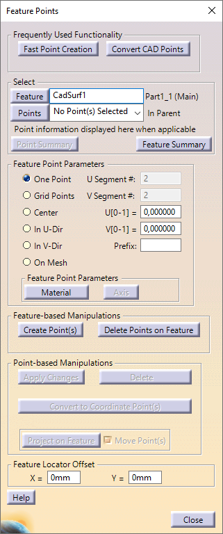
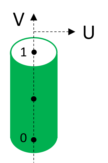
One Point: Create a Feature Point by specifying the U and V values (0-1). Feature Points associated with a surface have a U and V value which define their relative location on the surface. The U and V direction indicator will show on screen while points are being created. These Feature Points will have associated vectors that are normal to the surface.
Note:
•Feature Point vector directions are defaulted to follow the material direction, or normal to the surface. When Feature Points are created on a feature, 3DCS automatically determines the "outside of material" direction and defaults the Feature Point vectors accordingly. The user may still reverse the vector directions if desired using the Switch Directions checkbox in the Feature Points dialog.
•As a Feature Point/Coordinate Point is created or modified, it is automatically displayed graphically while that point is active, regardless of whether ![]() Show Points is on or off.
Show Points is on or off.
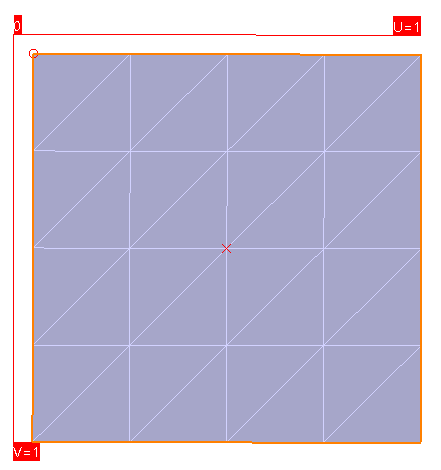
Grid Points: Create a grid of Feature Points on a surface or cylinder by specifying the number of segments with the U Segment # and V Segment # input fields.
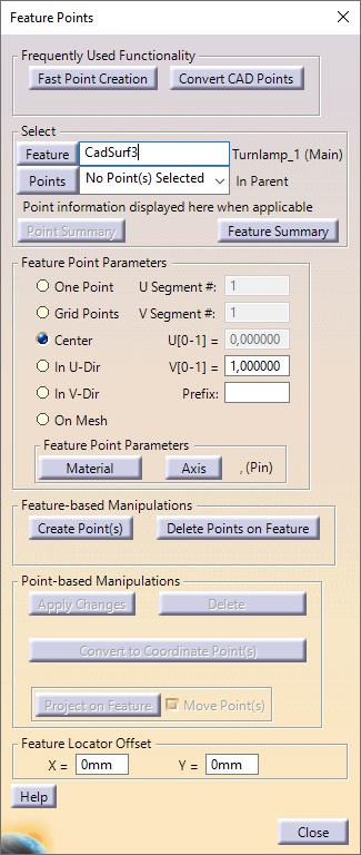
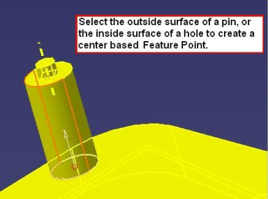
Center: Create a Feature Point on the axis of a pin or hole by specifying the V value (0-1). The V value defines the relative distance of the Feature Point from the base of the pin or hole.
Note: When a Feature Point is created at the center of a hole (internal feature) or pin (external feature), 3DCS decides whether the feature should be treated as a hole or a pin based on the nature of the feature itself.
In U-Dir: Create a set of Feature Points along the U direction line by specifying V Segment # input field and the U value (0-1). The V Segment # defines the number of segments in the set of Feature Points and the U value defines the relative distance of the set of Feature Points along the U direction line.
In V-Dir: Create a set of Feature Points along the U direction line by specifying U Segment # input field and the V value (0-1). The U Segment # defines the number of segments in the set of Feature Points and the V value defines the relative distance of the set of Feature Points along the V direction line.
On Mesh: Create Feature Points at all of the intersecting points on the surface mesh.
Prefix: Text input field that defines a prefix to be added to the name of any points that are created.
•Material: Reverses the vector of the Feature and all Feature Points on the selected feature.
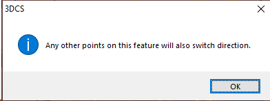
•Switching the direction of a cylindrical feature will only change the Feature Points created on the cylinder's axis (Center).
Switch Direction Procedure:
1.Select [Feature] and then select a feature in the Graphics window or Navigation tree.
2.Select [Switch Direction] (checked on).
3.Select [Create Point].
Switch Direction Procedure:
4.Select [Feature] and then select a feature in the Graphics window or Model Navigator.
5.Select [Switch Direction] (checked on).
[Create Point(s)]: Create the active point(s) from the Feature Point dialog. The user can then continue to create points, or [Close] the dialog.
Note:
•If the active point already exists or if there is a Feature Point already in, then [Create Point(s)] will not create a point.
[Delete Pts on Feature]: Delete all Feature Points on the active feature.
[Apply Changes]: Apply the requested changes for the point selected in the drop-down list. These changes include Feature Point Parameter, U and V values, point name, etc.
[Delete]: Delete all the points in the drop-down list.
[Convert to Coordinate Point]: Convert all the Feature Points in the drop-down list to Coordinate Points.
Note:
•At least one Feature Point must be selected and it must be the point selected in the drop-down list.
[Project on Feature]: Projects all the Feature and Coordinate Points in the drop-down list onto the active feature
Note:
•If the Move Original Point option is unchecked, new Feature Point(s) will be created on the active feature with no links to the MTMs (Moves, Tolerances, and Measures) of the points they were projected from. Any Coordinate Points in the drop-down list will be converted to Feature Points.
•If the Move Original Point option is checked, the Feature and Coordinate Point(s) in the drop-down list will move to the active feature as Feature Point, maintaining links to MTM’s. Any Coordinate Points in the drop-down list will be converted to Feature Points.
Best Practices - Project Feature Point: Update or Edit Feature Point
1.Select ![]() Feature Point on the 3DCS Model Creation Toolbar or navigate to it in the 3DCS drop-down list (Features -> Feature Point).
Feature Point on the 3DCS Model Creation Toolbar or navigate to it in the 3DCS drop-down list (Features -> Feature Point).
2.Select [Point] and select the Feature Point/Coordinate Point to be projected.
3.Select [Convert to Coordinate Point] to convert the Feature Point into a Coordin5+ate Point.
4.Select [Feature] and select the new surface on which the point will be projected.
5.Make sure the Move Original Point option is selected to move the original point onto the new surface.
6.Select [Project on Feature] to project the point onto the new surface.
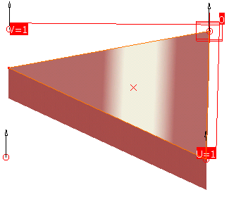
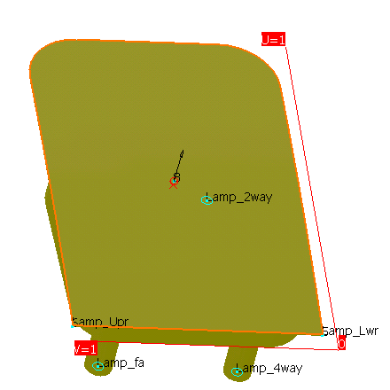
Feature Locator Point: When a feature is selected in an MTM or GD&T, the function will be using the Feature Locator Point associated with that feature. The Feature Locator point is not a user-created point and does not appear in the Points dialog. By default the point is at the center of the feature (calculated from the average of Mesh Nodes), but its location can be modified with the X and Y input fields when the feature is active in the Feature Point dialog. The Feature Locator Point location is represented by a red x when an existing feature is highlighted (see below.)