The •Any point created using the Points dialog is considered a Coordinate Point, however, you will be able to view Feature Points in the dialog as well. Coordinate Points are static points. They can be used in a Move, Measure or GD&T but have no reference to any features. •Feature Points are indicated in the Description area by the words "Feature Point". Feature Points are linked to a feature. They are not editable in the Points dialog and only show their X,Y,Z coordinates or its I,J,K associated vector.
To show the point(s) in the Graphics Window, with their vectors, select the point(s) in the Points dialog. The highlighted point with arrows representing the point's associated vector and start angle will be displayed on the part. The "start angle" determines where the unit circle begins in the plane of a circular feature. It is commonly used to determine Hole-Pin Float Angles when using certain float distribution types within a move. The display will show an axis system imposed about the center point of a circle. The vector direction is indicated, along with a "0" direction, and also a "90" direction. The "0" direction is the starting point for the unit circle, and the "90" direction simply tells the user which way the unit circle is swept around the center point. |
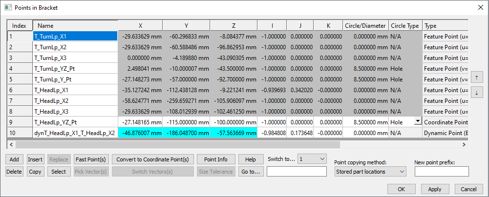
Name: Defined name of the point. Select in the Name field to change the name of the point. Select OK or Apply to apply the changes.
XYZ: Displays the coordinates of the point. Only Coordinate Point's XYZ coordinates can be changed..
ijk: Display the point's vector direction. Only Coordinate Points ijk vectors can be changed.
Circle/Diameter: Displays the point's diameter size. Type in a value and select [Apply] to add a diameter size to the point. Change the type to Hole or Pin type, or change to N/A to remove the Size.
Size Tolerance (Circle Tolerance -This is a Legacy option): To activate, go into the 3DCS Preferences under MTM Defaults and activate the "Create Size Tolerance for hole/pin Points automatically. Select Size Tolerance to apply a size tolerance to the selected point.
Type: Displays the type of point. The different types of points are: Coordinate Point, Feature Point and Dynamic Point. This also shows the point's size and the Dynamic Point's control points
Description: Type in a description about the point. This can be displayed in the Contributor Results and the Analysis Report.
Status: Displays the current Display status. If the Point is set to ON, the Point is shown in the graphics; if the Point is set to OFF, the point is hidden in the graphics. Right-click on a point and select Hide/Show Feature to toggle the Point's display. Using a ON or OFF point in any Move, Measure or GD&T will not change the how the MTM/GD&T performs.
Parameters
Switch To: Allows the user to reorder a point by moving the highlighted point to the selected Index. Use the ![]() and
and ![]() to move the points in the list.
to move the points in the list.
[Add]: Adds a Coordinate Point to a part. The point will initially have coordinates of (0,0,0) and is always added to the end of the point list.
[Delete]: Removes the highlighted point(s) from the part's point list.
[Insert]: Functions the same as [Add], but it will insert a Coordinate Point in the list after the highlighted point.
[Copy]: Creates a copy immediately below the selected point.
[Replace]: Replaces the coordinates and directional vector of the highlighted Coordinate Point with those of a selected Coordinate Point. Clicking on [Replace] activates the Graphics Window and allows the user to select the point to read the new coordinates and directional vector from.
[Select]: Allows the user to pick one or more points from the component geometry in the Graphics Window. Clicking on [Select] activates the Graphics Window and allows the user to select point(s) with the mouse. If the point(s) are in the activated part's point list, it will simply highlight those points in the point list. If the point(s) are in another part, a copy of those point(s) will be added to the part's point list. The user has two options when selecting point(s):
Point copying method: Instantly copies the selected Point(s). Applies a name "Copy_of_" to the new point.
[Fast Pts]: Opens the Fast Point Creation dialog.
[Pick Vectors]: Allows the user to edit the vector direction of the highlighted Coordinate Point. From the Pick Vector dialog, the user can specify either: Type In, Two Pt, Normal, or PickPtDir.
[Convert to Coordinate]: Converts the highlighted Feature Point to a Coordinate Point. This will remove the link from the surface the Feature Point was created on.
[Switch Vectors]: Switches the sign of the I,J,K values for the associated vector of the highlighted Coordinate Point.
| Note: Only works on when a Coordinate Point is highlighted and when the direction type is Type-In. [Switch Vector] cannot be selected when a Feature Point is highlighted. |
[Point Info]: Loads the Point Info dialog for the highlighted point.
[Size Tolerance]: Creates a pin or hole with size tolerance for the highlighted Coordinate Point. The nominal diameter or size tolerance information of pins or holes associated to Feature Points cannot be modified. Find more information about Size Tolerance in the Tolerance section of the help manual.
[Help]: Opens 3DCS Help Document for Points dialog.
[Go to...]: Highlights the Point with matching name.
Best Practices
•Using Edit Point dialog with Stored Part Location: Starting from the Design Position part, and another part was already moved away from the Design Position part and contains the points for the Move:
1.Open the Edit Point dialog on the Design Position part/sub-assembly.
2.Make sure the Copy Point Method is set to Stored Part Locations.
3.Select the [Select] button and select the points on the translated part.
4.When prompted, select Yes when copying the Point using Stored Coordinates.
Note: Select any of the column headings to sort the points by that column. This function only changes the view of the points, the points will retain their Index value. |