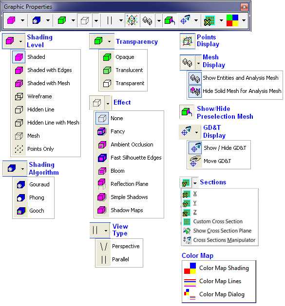
View menu allows the user to displays the geometry in various display modes. Most of these options are also available in the Graphic Properties toolbar.

This option shades the part with the edge lines hidden. Since they are hidden, the edge lines are unselectable.
This option shows both the shaded part and the part's edges (wireframe.)
Shaded with Mesh is simply regular shaded mode with the underlying display mesh shown on top of it.
This option shows only the part's edges (wireframe) without any shading.
![]() Hidden Line
Hidden Line
This option hides both the tessellation lines and the wireframe hidden by part shading. No shading is actually shown. New in 6.3.0.
Hidden Line with Mesh is the regular Hidden Line display with the underlying display mesh shown on top of it.
This option displays the part with the facets or tessellation shown.
This option only displays the Coordinate points, Feature points, and CAD points of the part.
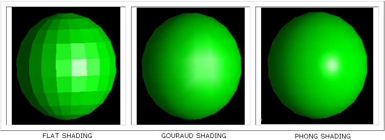
Also referred to as smooth shading, this rendering option causes faceted objects such as shells, meshes and NURBS surfaces to be displayed as if they were smooth, curved surfaces. Lighting interpolation only applies if there are one or more lights in the scene. If lighting interpolation is off, then 'flat shading' will be performed, which causes each facet to have a single uniform color. There are three types of lighting interpolation: gouraud, phong and gooch.
The gouraud shading algorithm computes the light at each vertex, and then interpolates that value across the face. It is also the default method used to draw shell/mesh/surface faces if a light is present in the scene. Gouraud shading is almost always accelerated by underlying 3D hardware. It has some shortcomings, where specular highlights may not be rendered accurately, and 'phantom' triangle artifacts can appear, where the underlying triangulation of the model can sometimes be noticed.
The phong shading algorithm computes the light on a per-pixel basis. This results in more accurate display of curved surfaces, and enhances the display of specular highlights.

Gooch rendering is a non-photorealistic shading model that has become popular in recent years because it draws from some of the techniques used in technical illustration.
In addition to taking colors from physics-based lighting equations, gooch rendering also blends them with a color scheme that uses artist's techniques. Highly lit surfaces are assigned a "warm" color, whereas areas with facing away from the light are given a "cool" color. The total effect is that lighting becomes a color shift in addition to the usual light to dark transition.
3. Transparency
This option shows any shading or mesh as opaque. New in 6.3.0.
This option shows any shading or mesh as translucent. New in 6.2.0.
This option shows any shading or mesh as transparent. Added for use with Cross Section view. New in 6.3.0.
![]() None - no effect will be applied.
None - no effect will be applied.
![]() Fancy - This option allows a quick activation of Ambient Occlusion, Fast Silhouette Edges, and Bloom.
Fancy - This option allows a quick activation of Ambient Occlusion, Fast Silhouette Edges, and Bloom.
![]() Ambient Occlusion - If checked, shading is applied when nearby objects or occluders would prevent some portion of ambient light from reaching a surface.
Ambient Occlusion - If checked, shading is applied when nearby objects or occluders would prevent some portion of ambient light from reaching a surface.
![]() Fast Silhouette Edges - If checked, enables the drawing of fast silhouettes where the difference between z-buffer values of neighboring pixels is greater than a certain threshold.
Fast Silhouette Edges - If checked, enables the drawing of fast silhouettes where the difference between z-buffer values of neighboring pixels is greater than a certain threshold.
![]() Bloom - When enabled, the bright objects will begin to "bleed" into darker ones, simulating the imperfect focus inevitable with the human eye or any other type of lens.
Bloom - When enabled, the bright objects will begin to "bleed" into darker ones, simulating the imperfect focus inevitable with the human eye or any other type of lens.
![]() Reflection Plane - If checked, reflections against the floor are rendered.
Reflection Plane - If checked, reflections against the floor are rendered.
![]() Simple Shadows - If checked, shadows that are cast on the floor will be rendered. This is a limited functionality and shadow maps are recommended. Simple shadowing is sometimes referred to as fake shadowing, i.e. it does not rely on interpolation. Rather the shadow effect is achieved through use of texture maps.
Simple Shadows - If checked, shadows that are cast on the floor will be rendered. This is a limited functionality and shadow maps are recommended. Simple shadowing is sometimes referred to as fake shadowing, i.e. it does not rely on interpolation. Rather the shadow effect is achieved through use of texture maps.
![]() Shadow Maps - If checked, shadows that are cast on faces are rendered.
Shadow Maps - If checked, shadows that are cast on faces are rendered.
5. View Type
In a perspective view, grid lines converge to a vanishing point. This provides the illusion of depth in the viewport. Perspective projection makes objects farther away look smaller.
Parallel views are also called orthogonal views in some systems. In a parallel view, all the grid lines are parallel to each other, and identical objects look the same size, regardless of where they are in the view.
6. Points Display
![]() Show Points
Show Points
This function shows or hides all Coordinate and Feature points in the model.
7. Mesh Display
![]() Show Entities and Analysis Mesh
Show Entities and Analysis Mesh
This function shows or hides the model's DCS created entities such as circles, lines, and features. New in 6.3.0, this function also shows or hides deviated mesh (Analysis mesh).
![]() Hide Solid Mesh for Analysis Mesh
Hide Solid Mesh for Analysis Mesh
This function hides or shows the nominal solid surface mesh (Nominal mesh) when deviating or sweeping the Analysis mesh.
8. Show/Hide Preselection Mesh
![]() Show/Hide Preselection Mesh
Show/Hide Preselection Mesh
This function shows or hides the mesh when mousing over a part. Will also highlight features of that part.
Note: Users can experience some confusion using this function with other hide/show functions together. The following table shows how one hide/show or activate/deactivate function may affect another and the results for every scenario. The results shown in red and green correspond to the point or feature being shown or hidden (Example: If Show Entities and Analysis Mesh is off and Show/Hide DCS Points is on then the points will be hidden). The gray areas are not applicable for the functions in use.

9. GD&T Display
![]() Show / Hide GD&T
Show / Hide GD&T
This function shows or hides any GD&T callouts created in the model. New in 6.3.0.
This option allows any GD&T callouts created in the model to be moved. Only the callout is moved, the link to the feature remains unchanged. New in 6.3.0.
Note: The ![]() Show/Hide GD&T and
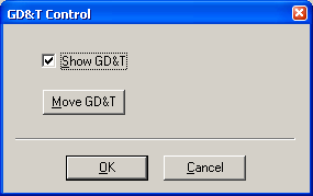
Show/Hide GD&T and ![]() Move GD&T options are also available in the GD&T Control dialog, opened from the Graph window by pressing <Ctrl><Alt><Shift>G.
Move GD&T options are also available in the GD&T Control dialog, opened from the Graph window by pressing <Ctrl><Alt><Shift>G.
Here the GD&T callouts can be turned on, using the Show GD&T button, and reposition around the part, using the Move GD&T button.

10. Sections
![]() ,
, ![]() ,
, ![]() View Cross Section
View Cross Section
The Cross Section function shows the user the cross section of the model. The cross section can be cut normal to grid, along X, Y, or Z direction.
This function allows the user to define a customized section plane in the Graph window.
![]() Show Cross Section Plane
Show Cross Section Plane
This function shows/hides a section plane in the Graph window.
![]() Cross Sections Manipulator
Cross Sections Manipulator
This function shows/hides the manipulator for all cross section planes in the Graph window.
11. Color Map
![]() Color Map Shading
Color Map Shading
This function activates color mapping on parts in the graph window.
![]() Color Map Lines
Color Map Lines
This function activates color map lines that represent statistical data for active measurements.
![]() Color Map Dialog
Color Map Dialog
This function allows user to configure settings for color mapping feature.