The
|
Specification:
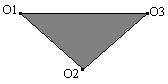
Object Points: The part (or assembly) to be moved.
O1: The first point on the part to be moved.
O2: The second point on the part to be moved.
O3: The third point on the part to be moved.
Target Points: The part or parts locating the object.
T1: The first point on the line.
T2: The second point on the line.
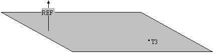
T3: A point on the plane.
Direction: A vector normal to the plane passing through Tgt3.
Description:
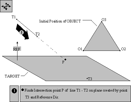
The target consists of two points that create a line, a point on a plane, and a vector that defines the plane. The object is a plane defined by three points. The object plane is moved to the target plane, the intersection of the line and the plane is the 4-way locator and the point on the plane is the 2-way locator.
The object is defined by points O1, O2 and O3.
The target points T1 and T2 forms the line which is projected onto the plane.

The target plane that locates the object is made up of target point T3 and the directional vector of the plane referred to as Reference direction.
Notes: 1. If AssocDir is selected, by default the direction will be the Associated Vector of Target Point # 3.
2. All associated vectors default to (0, 0, 1) if corresponding point is not selected.
Logic Description:
STEP 1: The line through T1 and T2 intersects the plane through T3 and normal to the Direction vector. The intersection point, IntPt, is calculated internally to the routine.
STEP 2: The object is translated to the target moving O1 to IntPt.
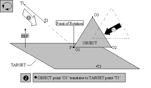
STEP 3: The object pivots about the intersection point until O2 falls on the line through the intersection point (IntPt) and the point on the plane (T3). This forms the axis of rotation for the next step.
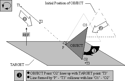
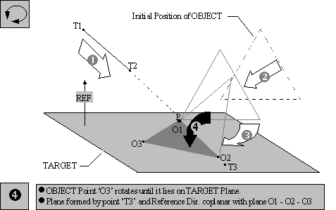
STEP 4: The object rotates about the line through IntPt and T3 until O3 lies on the target plane.
Note: Care must be taken when selecting the target line points and vector normal to the plane. If the line and plane do not intersect, either by design or through variation, the results may be unpredictable.
Once the object has been translated to the part (Step 1) and pivoted about the intersection point until O2 falls on the line through the intersection point, IntPt, and the point on the plane T3, (Step 2). The direction of rotation, which puts O3 on the plane, may not be predictable. It may be necessary to set O3 = O2 to get the object on the initially, then with a second move and an additional target point on the plane, rotate the object to the target plane.
Special Cases
Case 1
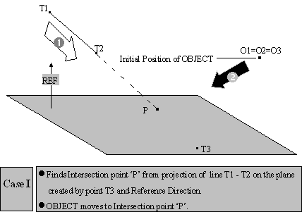
O1 = O2 = O3
In this case the object, which the routine thinks is a point, will only be translated to the intersection point P.
Case 2
O1 6 O2 = O3
In this case the object, which the routine thinks is a line, will be translated to the intersection point and pivot about the intersection point until Obj2 falls on the line through the intersection point (IntPt) and the point on the plane (Tgt3).
Case 3
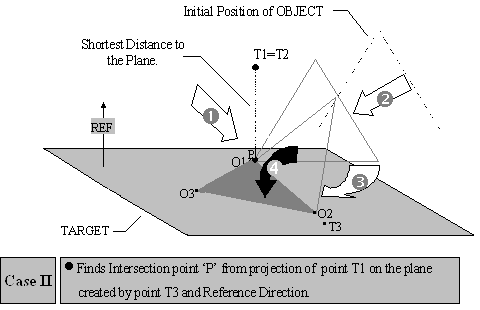
T1 = T2
In this case there is no line to intersect the plane, only a point in space. When this happens, the intersection point will be a point on the plane having the shortest distance to the point in space.
Note: T3 = P - In this case the location of object point O2 is uncertain but it lies on plane { T3, Ref.}.
Creating:
Selecting Ln-Pln Move displays the Ln-Pln Move dialog box along with the part name.
Object Point Definition:
This defines the object points for the move. Click on All Obj to select the three object points or click on O1 to select the first object point and O2 to select the second object point and click on O3 to select the third object point. The object points can be selected from different parts. Once the object point selection is made the point names are displayed in their respective boxes.
Target Point Definition:
This defines the target points for the move. Click on All Tgt to select the three target points or T1 to select the first target point and T2 to select the second target point and T3 to select the third target point. The target points can be selected from different parts. Once the target point selection is made the point names are displayed in their respective boxes.
Direction:
For a Ln-Pln Move the vector direction has to be defined.
Clicking on Direction brings up the edit direction dialog box. Select the method by which the vector will be created. Click on Close when done.
Exercise caution when defining the vector direction by the Two Pt or Normal methods. Make sure to lock the vector direction using the Type In vector method.
Also See: