The See also: |
![]() How to apply a GD&T Position Measure
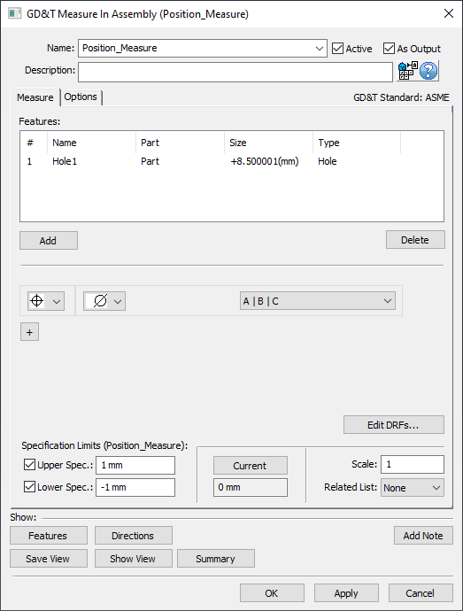
How to apply a GD&T Position Measure
Procedure: 1.Create a new 2.Assign the new GD&T Measure a Name and Description (if desired). 3.Select [Add] and select any features from the graphics window or the Model Navigator that will be included in the Position Measure. When finished select [OK][Close] in the Pick FeatureSelect dialog. 4.Select 5.Set the desired zone to Diametrical or Non-Diametrical (blank). 6.Select the desired DRF from the DRF list. Note: if needed, define the DRF by selecting [Edit DRFs...]. Also Create Datums if needed. 7.Set the Upper Spec. Limit and Lower Spec. Limit to whatever values this measure is meant to check against (typically found on Assembly level drawing). Note: Can also turn off Upper Spec. Limit and Lower Spec. Limit if desired.
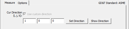
Options TabIf Non-Diametrical (blank) is selected, then the user may be required to input a custom direction.
|
|---|
![]() GD&T Position Measure Analysis - Diametrical
GD&T Position Measure Analysis - Diametrical
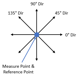
Single Point Analysis: The
Above: At Nominal these are the measure directions 3DCS will use for the four Point Distance Measure that combine into the Position Measure
Note: 3DCS does not display what these four directions of measure are for the
3DCS is not combining the four Point Distance Measures on a "per build" basis (like the Combination Measure does). Instead, 3DCS internally keeps these four measures and then only shows a single distribution at the end. The distribution shown is the one that returns the largest Recommended GD&T Value (see Recommended GD&T Value section for more details).
For an example case, we could have these four results:
In this case, the 90° direction has the largest Recommended GD&T Value so for the Note: Because 3DCS is only displaying Contributor Analysis results for one of the four directions, it is possible that there is a Contributor that is affecting the variation in one or more of the other three directions but is not displayed in the Contributor Analysis list for the measure because it is not adding variation to the measure direction that had the greatest Recommended GD&T Value.
Multiple Point Analysis: When using multiple points in the Features list of the GD&T Measure dialog, the
For an example case, we could try adding two points to the Feature list and get these results:
The 45° direction of Point 2 has the largest Recommended GD&T Value and therefore it will be the output for this
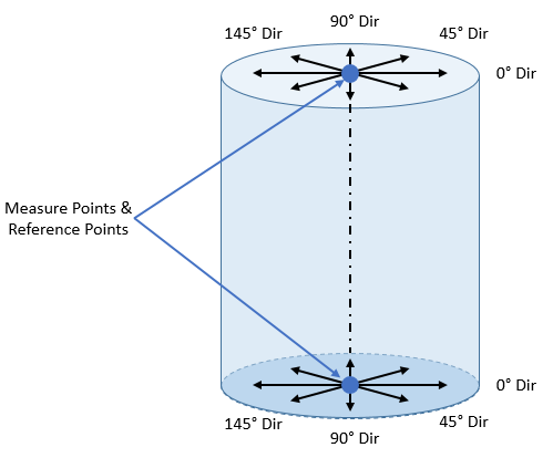
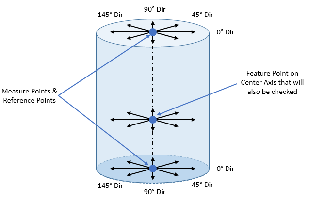
Single Axial Feature Analysis: An Axial Feature such as a pin or a hole can be selected in the Features list of the GD&T Measure dialog. If a Feature has no Feature Points on the Center of the Feature, then the
Above: At Nominal these are the measure directions and points at the axis's ends that 3DCS will use for the Point Distance Measures that combine into the Position Measure
For a single Feature without any Feature Points there will be eight total measures that the
For an example case, we could have these eight results:
The 0° direction of Axis End 1 has the largest Recommended GD&T Value and therefore it will be the output for this
If the Axial Feature also contains Feature Point(s) on its axis, the
For an example case, we could have these twelve results:
The 135° direction of Axis End 1 has the largest Recommended GD&T Value and therefore it will be the output for this
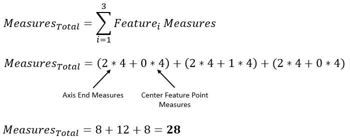
Multiple Axial Feature Analysis: Multiple Axial Features such as a pin or a hole can also be selected in the Features list of the GD&T Measure dialog. If a multiple Features are selected, then the
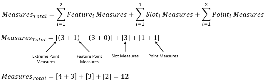
Example 1: 3 Features Feature1: 0 Center Feature Points Feature2: 1 Center Feature Point Feature3: 0 Center Feature Points
Example 2: 2 Features, 3 Points Feature1: 1 Center Feature Point Feature2: 0 Center Feature Points
For an example case, where we have two Features selected in the Features list and neither Feature has a Center Feature Point, we could have these sixteen results:
The 45° direction of Axis End 2 for Hole 1 has the largest Recommended GD&T Value and therefore it will be the output for this
|
|---|
![]() GD&T Position Measure Analysis - Non-Diametrical
GD&T Position Measure Analysis - Non-Diametrical
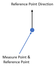
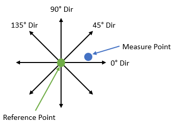
Single Point Analysis: The
Above: At Nominal. The measure direction 3DCS will use is the direction of the Reference Point
The
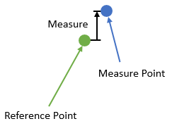
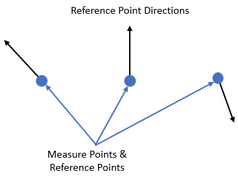
Multiple Point Analysis: When using multiple points in the Features list of the GD&T Measure dialog, the
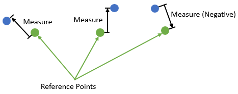
Above: At Nominal. The measure directions 3DCS will use are the directions of the Reference Points
3DCS is not combining the three Point Distance Measures on a "per build" basis (like the Combination Measure does). Instead, 3DCS internally keeps these three measures and then only shows a single distribution at the end. The distribution shown is the one that returns the largest Recommended GD&T Value (see Recommended GD&T Value section for more details).
For an example case, we could have these three results:
In this case, Point 3 has the largest Recommended GD&T Value so for the Note: Because 3DCS is only displaying Contributor Analysis results for one of the three points, it is possible that there is a Contributor that is affecting the variation in one or more of the other two points but is not displayed in the Contributor Analysis list for the measure because it is not adding variation to the point that had the greatest Recommended GD&T Value.
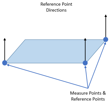
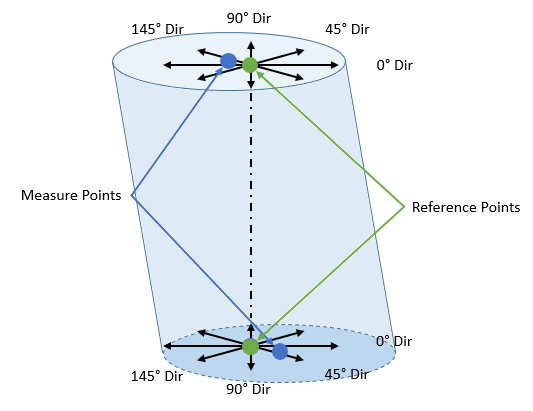
Single Feature Analysis: In accordance with ISO allowing a True Position callout to be applied to a flat face, a face can also be selected in the Features list of the GD&T Measure dialog for this case. If a face has no Feature Points on it, then the
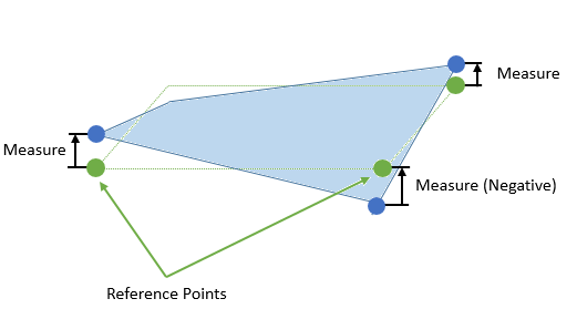
Above: At Nominal. The measure directions 3DCS will use are the directions of the Reference Points. The Measure Points are internally calculated by 3DCS to be the extreme points on a surface
For an example case, we could have these three results:
In this case, Extreme Point 2 has the largest Recommended GD&T Value so for the Note: 3DCS does not display what these three extreme points will be for the
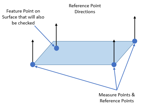
If the Feature also contains Feature Point(s) on its surface, the
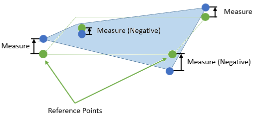
Above: At Nominal. The measure directions 3DCS will use are the directions of the Reference Points. The Measure Points are internally calculated by 3DCS to be the extreme points on a surface and the single Feature Point that is on the Surface
Above: At possible deviation. The Measure Points are measured from the Reference Points along the directions of the Reference Points. The Feature Point is also included in the results
For an example case, we could have these four results:
In this case, Feature Point 1 has the largest Recommended GD&T Value so for the Note: a slot in 3DCS is treated the same as a face in the
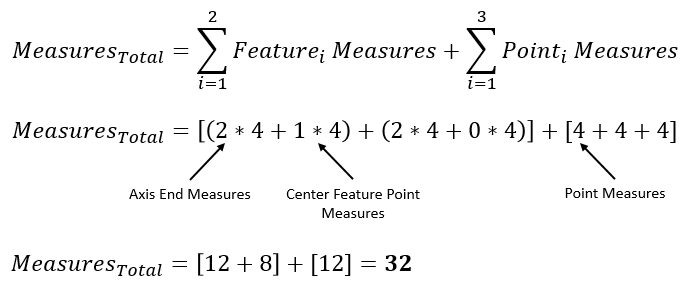
Multiple Feature Analysis: It is also possible to add multiple Features in the Features list of the GD&T Measure dialog. If multiple Features are selected, then the
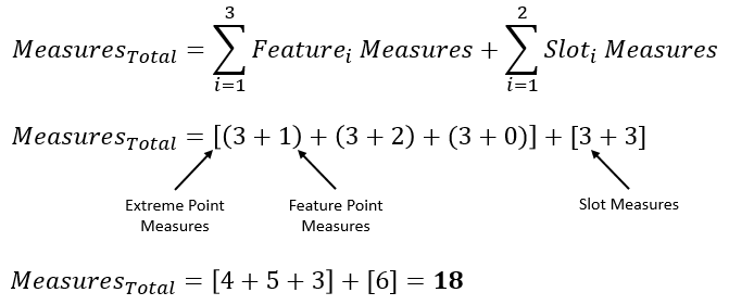
Example 1: 3 Planar Features, 2 Slot Features Feature1: 1 Feature Point Feature2: 2 Feature Points Feature3: 0 Feature Points
Example 2: 2 Planar Features, 1 Slot Feature, 2 Points Feature1: 1 Feature Point Feature2: 0 Feature Points
For an example case, where we have two planar Features selected and one Slot Feature in the Features list and neither planar Feature has a Feature Point, we could have these nine results:
In this case, Extreme Point 2 for Feature 2 has the largest Recommended GD&T Value so for the
|
|---|