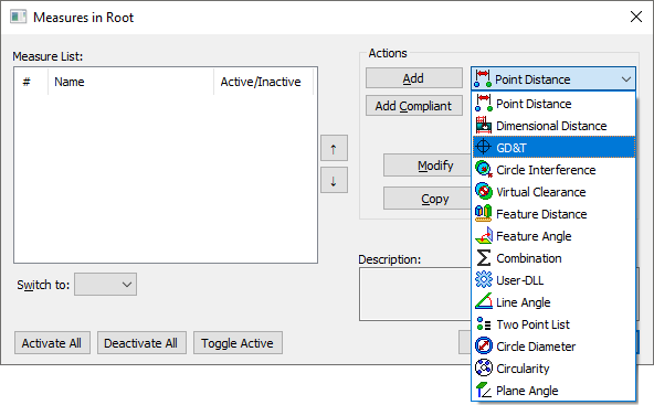
A GD&T Measure checks the variation of features relative to a Datum Reference Frame (DRF) according to GD&T standards. |
|
Within this Section:GD&T Measure Cases Common Parameters Edit DRFs Options tab |
Topics:
|
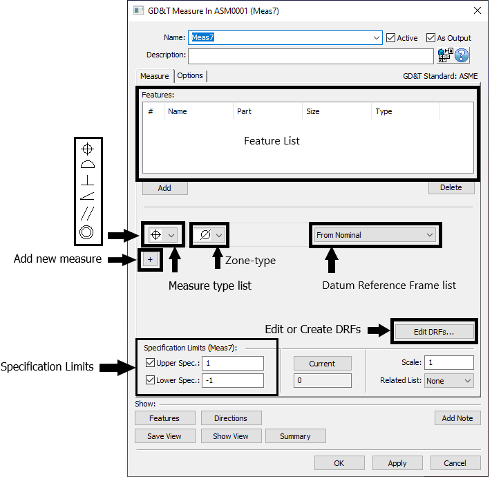
Feature List: Features used for the selected measure.
Measure type list: Users can change the measure type from the measure type lists. Only Position, Surface Profile, Perpendicularity, Angularity, Parallelism, and Concentricity are available as a measure type.
Zone type: Change the zone type of the measure. Diametrical or non-diametrical zones are available for applicable measure types.
Datum Reference Frame (DRF) list: If any DRFs have been created while creating GD&T or GD&T Measures in the part or assembly, the list of DRFs will be available in the drop-down list. Changing the DRF will affect the measure results.
From Nominal: Measures the feature relative to its Nominal location rather than relative to a set of Datums.
Edit DRFs: If no DRFs are available, users will need to define DRFs through the Edit DRF dialog. Datums are required to create functional DRFs and can be created in the GD&T dialog of an assembly or part level.
Specification Limits: Is the Upper and Lower Spec. Limits of the Measure. Typically the GD&T Measure will be used to check a bilateral tolerance zone so the Upper and Lower Spec. Limits will be the same value. For example, if checking a Profile of range 1, then the Upper and Lower Spec. Limits would be +0.5 and -0.5 respectively.
The Upper and Lower Spec. Limits can be activated or deactivated in a measure, showing only a N/A (Not Available) in the Simulation Window. |
Show Features: Highlights the features used in the measure list.
Show Directions: Displays a vector direction from the measure, if applicable.
Save View: Saves the current view of the part or geometry. Users can change the saved view by changing the view of the part in the Graphics window and selecting Save View again.
Show View: Displays the saved view of the measure. If no view is saved for the measure, no view will be shown; current view of the part is the current view.
Summary: Displays all information about the current selected measure, such as information about the DRFs or feature XYZ location.
Add Note: Add text or images that will be included in the report.
Note: Users will need to utilize the Editing File in External Editor dialog. Edit the note and then Save to File.
•If using Microsoft Word DO NOT CLOSE Word, return to 3DCS and select [Save to File] button.
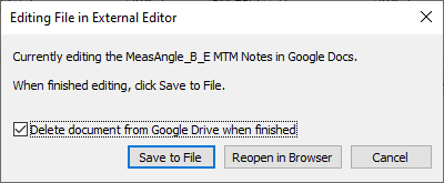
•If using Google Docs, edit the notes, return to 3DCS and select [Save to File] button.
oDelete document from Google Drive when finished - removes the Doc from the user's Google Drive.
Editing DRFs:
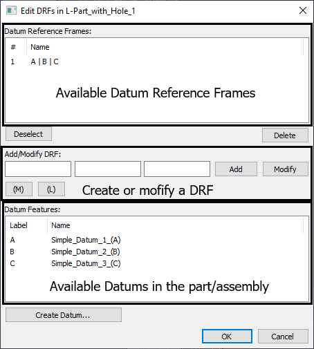
Datum Reference Frames: Displays the available DRFs in the part/assembly.
Add/Modify DRFs: Edit or create a new DRF. Users can also type in Datum labels.
•If adding, select a datum in Datum Feature list (below). If creating a shared datum (A-B), select the feature to add in the first field. Select the field and type "-B" or "A-B". (Adding a Datum with a Material Boundary will be ignored for GD&T Measures).
•If modifying an existing DRF. Select a DRF at the top. In the fields, select the datums to define a new DRF sequence. Select Modify when finished.
Datum Features: Lists the available Datums in the part or assembly.
Create Datum: Will open the GD&T dialog for creating a new Datum.
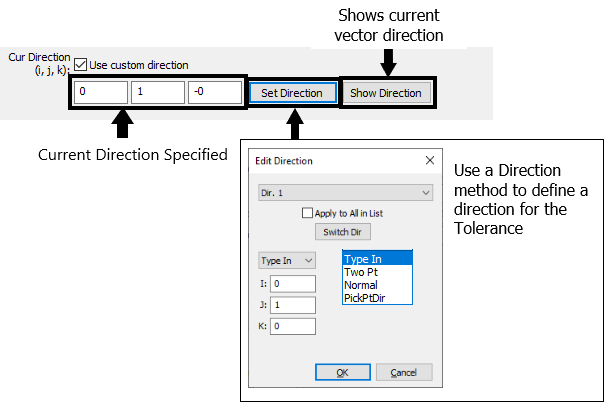
Custom Direction: If defining a GD&T Measure without a diametrical zone, 3DCS may require a direction to be defined. In the Options tab, activate Use custom direction.
Material or Boundary Condition:
GD&T is the general type of measure in the Measures list. After adding a GD&T Measure, the specific type of GD&T is selected within the GD&T Measure dialog.
GD&T Measures do not support Maximum Material Condition ![]() , Least Material Condition
, Least Material Condition ![]() , or datum shift. For example, for the following Position callout the GD&T Measure will not be able to account for the bonus allowable variation from the Maximum Material Condition
, or datum shift. For example, for the following Position callout the GD&T Measure will not be able to account for the bonus allowable variation from the Maximum Material Condition ![]() . Instead, it would be required to define the measure without the Maximum Material Condition
. Instead, it would be required to define the measure without the Maximum Material Condition ![]() .
.
Original GD&T Note:
|
GD&T Measure will be defined as:
|
Datum Shift:
The following Surface Profile callout cannot be entered into the GD&T Measure because of the allowable datum shift on the B datum feature coming from the Maximum Material Boundary ![]() in the DRF. The callout would instead need to be input as without the Maximum Material Boundary
in the DRF. The callout would instead need to be input as without the Maximum Material Boundary ![]() .
.
Original GD&T Note:
|
GD&T Measure will be defined as:
|
Adding feature points or using Update Geometry can affect the Measure. If a surface is being measured, the average center of the surface, represented by the Feature Locator Point, can change as feature points are added to that surface. Using Update Geometry can also change the average center if nodes are added or removed. Changing the average center can change the extreme points that are measured internally and thus affect the measurement.
Why Results Can Be Negative
While the purpose of each the ![]() GD&T Measure is to return a zone size for the specific GD&T type (for example, the zone size for a Surface Profile or True Position callout), it is possible (and very likely) that some of the results (typically half) provided by 3DCS will be a negative value. The results are expressed in this fashion so that the measure is a linear measure. The benefit of this being a linear measure is that the results for GeoFactor Equation-Based Analysis results and Contributor Analysis results will be much more useful/accurate for a linear measure (such as a Point-Distance Measure when Projected on Vector is used as the Dir. Mode) than they are for a non-linear measure (such as a Point-Distance Measure when Projected on Plane is used as the Dir. Mode). Because the output we really care about is what value the zone size is for the GD&T type we are using, 3DCS also returns the Recommended GD&T Value for all
GD&T Measure is to return a zone size for the specific GD&T type (for example, the zone size for a Surface Profile or True Position callout), it is possible (and very likely) that some of the results (typically half) provided by 3DCS will be a negative value. The results are expressed in this fashion so that the measure is a linear measure. The benefit of this being a linear measure is that the results for GeoFactor Equation-Based Analysis results and Contributor Analysis results will be much more useful/accurate for a linear measure (such as a Point-Distance Measure when Projected on Vector is used as the Dir. Mode) than they are for a non-linear measure (such as a Point-Distance Measure when Projected on Plane is used as the Dir. Mode). Because the output we really care about is what value the zone size is for the GD&T type we are using, 3DCS also returns the Recommended GD&T Value for all ![]() GD&T Measures.
GD&T Measures.
As an example, some users may expect the results for a specific ![]() Surface Profile Measure to look like the image below.
Surface Profile Measure to look like the image below.
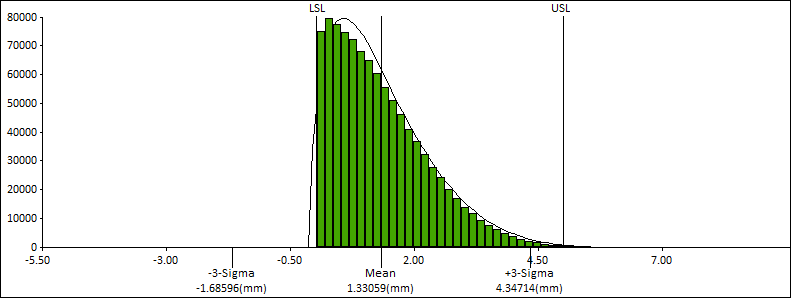
Above: A set of results for a possible GD&T Measure if the results were always expressed as a positive number.
The results above are expressing the zone on a per build basis meaning that if the surface is +0.5 or -0.5 away from its nominal location, then 3DCS will return a value of 1 because this is the positive number that represents the zone size for either of those possible surface deviations. This methodology has a few drawbacks. First, as mentioned above, by forcing the value to always be positive the measure has a high probability of being nonlinear which will make the GeoFactor Equation-Based Analysis results and Contributor Analysis results less useful. Second, by outputting a non-normal curve we now become reliant on the curve-fitting potential for this type of curve which will not be as accurate or confident as the results we will get if we aim for a normal distribution as shown below.
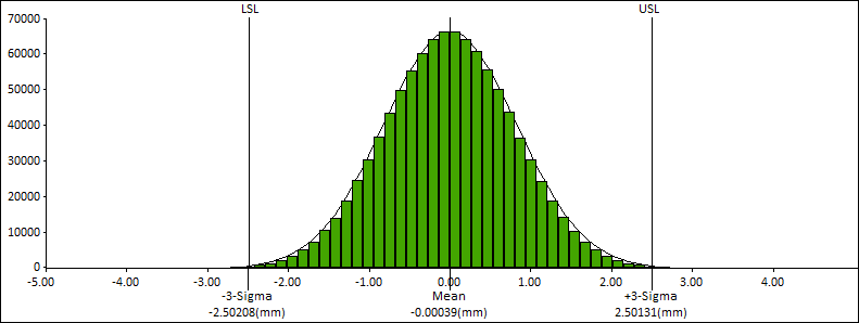
Above: A set of results for a possible GD&T Measure if the results were allowed to be expressed as a positive or negative number.
The results above are no longer expressing the results on a per build basis, however by taking positive and negative results we have a much greater chance of maintaining linearity and also getting a normally distributed output.
For the examples above, the input is a single tolerance of 5mm. For the first method 3DCS would predict the need for a zone size of 5.305mm on the drawing. For the second method the zone would only be 5.004mm. The second method returns a value much more in line with expectations given the input.
Notes:•The purpose of the GD&T Measure is assumed to be to check assembly level variation and determine what value to put into a Feature Control Frame at the assembly level. In the Analysis Window, a new result is available called Recommended GD&T Value. This is the value 3DCS is recommending to put in the Feature Control Frame for the measured feature(s). |