Later on, we will want to use GD&T to add variation to the Bracket . These tolerances add variation to features of the part. Because Coordinate Points are not associated with any features, Coordinate Points will not vary with GD&T unless directly selected in the GD&T. So, we have to convert the Coordinate Points to Feature Points by projecting the points onto features.
•Navigate to the Points section for the Bracket in the Navigation Tree.
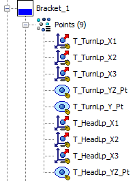
Similar to with Feature Points, for Coordinate Points 3DCS also uses different icons to communicate more information about the point through the Navigation Tree. The three icons used for Coordinate Points are the following:
![]()
![]() Coordinate Point with no Size Associated
Coordinate Point with no Size Associated
![]()
![]() Coordinate Point with Pin Size Associated
Coordinate Point with Pin Size Associated
![]()
![]() Coordinate Point with Hole Size Associated
Coordinate Point with Hole Size Associated
Coordinate Points can be used to simulate geometry that is not in the model, including pins and holes. As a result, 3DCS grants users the option to associate a size and type to a Coordinate Point. As mentioned above, we do have geometry that we would like to associate our Coordinate Points to, so our next step is to project these points onto their respective features.
•Click the ![]() Feature Points button to open the Feature Points dialog.
Feature Points button to open the Feature Points dialog.
•Make sure the Feature Point ParameterPoint Method is set to One Point.
•Click the [Points][Select Point(s)] button in the Feature Points dialog then select the point T_HeadLp_X3 on the Bracket. The point may be selected in the graphics or in the tree.
•Click [Close] to close the Select dialog and the Feature Points dialog will reopen.
•Click the [Feature][Select Feature] button in the Feature Points dialog then select the highlighted surface on the Bracket shown in the image below.
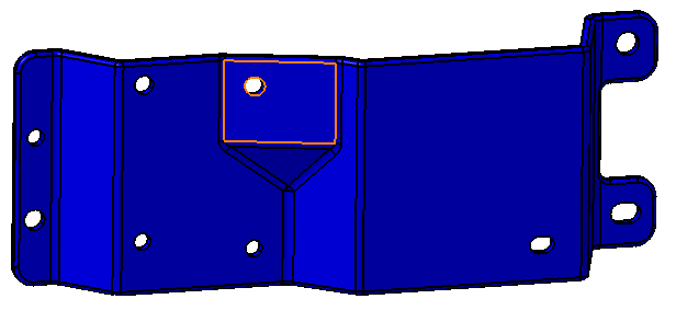
•Make sure that the box for Move Point(s) is checked. If this is off, it will create a new point instead of moving the original point.
•Click [Project on Feature].
The steps to project a point onto a surface are summarized in the image below. Your CadSurf number may be different.
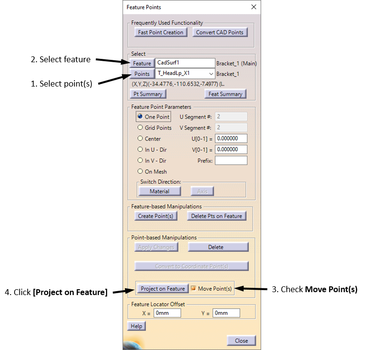
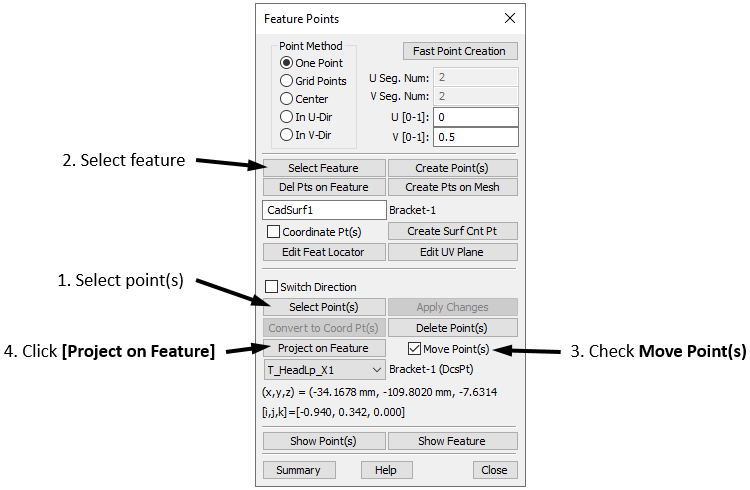
•Repeat this process to project the next five face points in the Bracket onto their respective surfaces. The surfaces to use are shown in the image below.
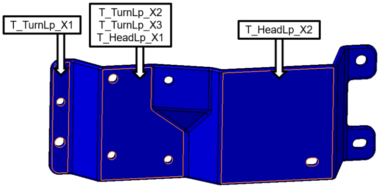
Next we must project the pin center points onto their respective holes in the Bracket.
•Click the [Points][Select Point(s)] button in the Feature Points dialog then select the point T_TurnLp_YZ on the Bracket. The point may be selected in the graphics or in the tree.
•Click [Close] to close the Select dialog and the Feature Points dialog will reopen.
•Click the [Feature][Select Feature] button in the Feature Points dialog then select the hole that corresponds to this point. It is shown in the image below.
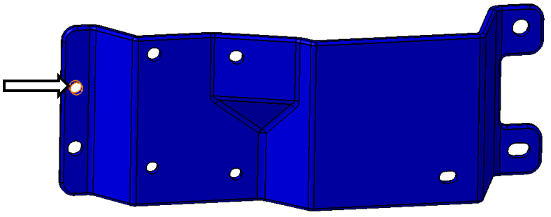
•Make sure that Center is selected in the Feature Point Parameters section instead of One Point. If One Point is selected then the point will be projected onto the surface of the hole rather than the center.
•Similar to before, ensure that Move Point(s) is checked and then select [Project on Feature] to project the point onto the center of the hole.
•Repeat this process to project the remaining two hole points in the Bracket onto their respective holes. The holes to use are shown in the image below.
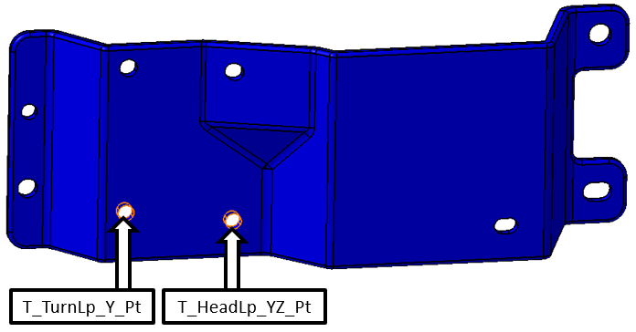
•Click [Close] in the Feature Points dialog.
•Click the ![]() Points button then select the Bracket.
Points button then select the Bracket.
Next we must project the pin center points onto their respective holes in the Bracket.
The Points dialog for Bracket should now show "Feature Point" in the Description of all pointshave gray boxes for all columns except Name and Description. Feature Points do not allow the user to directly edit the coordinates or vectors.
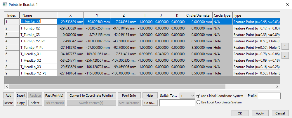
•Close the Points dialog.