The
|
|
See Also:
|
|
Specification:
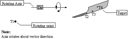
Direction: A vector defining the rotating axis that rotates the object to the target.
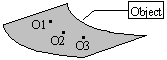
Object Points: The part (or assembly) to be moved.
O1: The first surface point on the part to be moved.
O2: The second surface point on the part to be moved.
O3: The third surface point on the part to be moved.
On: The n-th surface point on the part to be moved.
Target Points: The part or parts locating the object.
T1: The rotational point. Used with the direction vector to create the axis of rotation of the object to the target.
T2: The first point on the target. This point corresponds with Obj1.
T3: The second point on the target. This point corresponds with Obj2.
Tn+1: The n+1 point on the target. This point corresponds with Objn.
Description:
The object surface can be defined by any number of points from Obj1 through Objn selected appropriately on the object.
Point Tgt1, the rotating point, along with the direction, form the rotating axis about which the object is rotated. The target points are picked on the target surface depending on the number of object points picked.
The target point T1, which is the notational point and the direction, which is a vector, define the rotating axis that rotates the object to the target.
Notes: 1. If AssocDir is selected, by default the direction will be the Associated Vector of Target Point # 1.
2. All associated vectors default to (0, 0, 1) if corresponding point is not selected.
The target points are defined by the number of points defined on the object. Here the object surface is defined by three points, hence the target is defined by four points T1 (point of rotation,) T2, T3 and T4.
Logic Description:
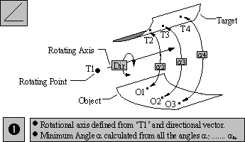
STEP 1 The notational axis is generated from point T1 and the directional vector. The angles a2, a3 and a4 between the Object points O2, O3 and O4 and Target points T2, T3 and T4 are calculated. If n number of object points are selected then angles from a through an+1 are calculated. The minimum angle a is then determined from among all the angles calculated.
Calculation:
a = Angle between point 'O1' and 'T2'.
a = Angle between point 'O2' and 'T3'.
an = Angle between point 'On' and 'Tn+1'.
Then a = Min.{ a, a , a4,....... an }
STEP 2 The object then rotates about the notational axis until it reaches the minimum angle 'a' that is determined from all the angles between the object and target points.
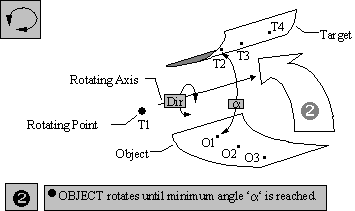
Note: An additional move may be needed to put the object in a preliminary position prior to rotation.
If the nominal angle of rotation is 180°, the direction of rotation may differ with each simulation. The calculated angle is always less than or equal to 180°. If you expect the object to rotate clockwise and, due to variation, the clockwise angle measures 182°, the object will rotate counterclockwise 178°.
If target and object points are not the same for the nominal build, the object may appear to be moving incorrectly under certain conditions (either interfering or not touching the surface). The object is actually moving to the matching point.
Creating:
Selecting R-Touch Move displays the R-Touch Move dialog box along with the part name.
Object Point Definition:
Clicking on the Add button next to Object Points brings up the Click Graph window dialog box. This lets you pick the object points from the Graph window. Select all the points required for the move. The object points can be selected from different parts. There is no limitation for the number of points. Click on Close when done to return to the move dialog box. The list box under Object Pt. displays the names of all the object points selected.
•To Delete any object point select the point in the list box and click on Del.
•A Key-in box lets you key-in the name of the point in order to select it.
•Click on the Order box to display the order of the object points selected.
Target Point Definition:
Creating the target points is performed the same way as the object points. Refer to the above section.