The purpose of the
|
There are two Modes in which this move can be used to locate & deform over-constrained object to primary locators:
Auto Bend: when you want to allow automated selection of the bending lines.
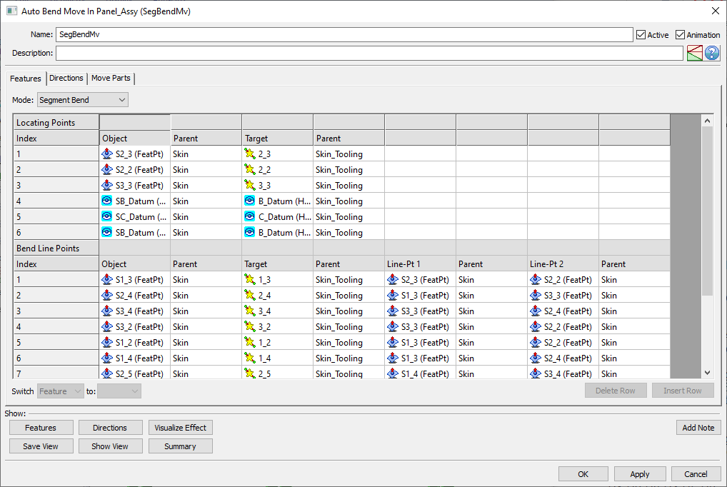
Segment Bend: when you want to control selection of the bending lines yourself.
The Auto Bend mode will initially locate the object part(s) on the first 3 Primary points and specified Secondary and Tertiary points, as in a Six-Plane Move. Additional primary object points establish triangle patches that will be bent to the target surfaces defined by the target points and vectors. All points within the triangle patches will be transformed accordingly. The Secondary and Tertiary points, including static points of slots, will be located in accordance with the initial move and will not be modified by subsequent bend planes, unless:
•The bending plane vector and the Secondary or Tertiary locator vector have a common component (their vectors overlap).
•The Secondary and Tertiary locators are included in one of the bending triangles.
The Auto Bend routine is similar in concept to the Segment Bend routine but provides an automated method to select bending lines. The bending segment is selected based on the closest point-line distance between a bending point and a two-previous-valid-bending-point line.
Process
1.The component(s) are first moved to the target with the first six object-target point pairs. (Internally uses the Six-plane move.)
2.The object features are then deformed based on the 7th to nth bending points. Each bending segment is automatically selected based on the closest point-line distance and the validity of the previous bend points. The axis line for each bend is internally determined by selecting a line of rotation from a number of candidate lines that are possible. The final selection is the line closest to the bend point (7th - nth) that has been previously located to its target. (Tip: When ordering the 7th - nth points, start with a bend point near one of the first three (1st to 3rd) and then work outward towards the edges.)
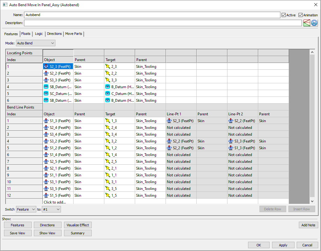
Features Tab
Locating Points list includes the first 6 object-target point pairs:
1st to 3rd - Three primary points
4th and 5th - Two secondary points
6th - One tertiary point
Bend Line Points list includes the 7th - nth object-target point pairs and the bend line points. The 7th to nth point pairs are additional primary points defining a sequence of bend deformations. If these points are selected in such order that calculating a bend line is not possible, the 'Not calculated' message appears in the dialog (see above).
The user defines the sequence of bend deformations by the order of the 7th through the nth points. These are the list of object points that are intended to deform to their respective target. It is generally recommended to start with a small central triangle and progress outward to the corners and edges. If the bend locations are defined out of order, object points may not touch on their respective targets. It is strongly recommended to create object-to-target gap measurements to verify the move.
Locating Points (rows from 1 to 6) can only be deleted using the keyboard Delete key
Floats Tab: The Auto Bend move offers floating options similar to the Six Plane move.
Logic Tab: The Auto Bend move can incorporate conditional logic options.
Directions Tab
Each target feature selected under the Features Tab will get assigned a direction under the Directions Tab.
Users can change the directions used between Assoc Dir, Type In, Two Pt, Normal, PickPtDir, or Auto, based on the situation. The directions are assigned in order:
1st to 3rd - Three vectors for the first three primary target points
4th and 5th - Two vectors for secondary target points
6th - One vector for the tertiary target point
7th to nth - Vectors for the additional primary target points
Move Parts Tab
At least one component should be selected for the Move Parts list.
Frequently Asked Questions:
When adding Bend Line points in the Auto-bend move, do I need to have those points as Feature Points linked to the surface that will be deformed?
The Segment Bend mode behaves similarly to the Auto Bend mode except for the bending lines selection - here it is done manually by the user by selecting points for Line-Pt 1 and Line-Pt 2.
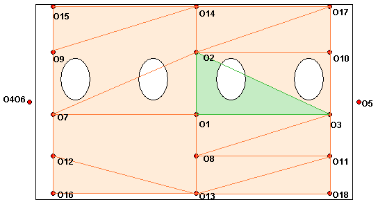
Example: The example below is a relatively thin plate with eighteen points distributed across its surface. The target surface is similarly configured.