A report can be generated when running a Simulation to show the
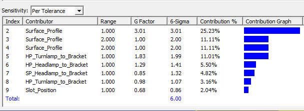
The Contributors can be show in the list by Tolerance or by their Feature. Per Tolerance: If a tolerance has more than one feature used, Per Tolerance will combine all Features into one Contributor and calculates the RSS (Root Sum Square) results of all contributors in the list. Per Feature: Will display all features used in the GD&T separately. Each feature will have a GeoFactor and 6-Sigma value. |
See AlsoHigh-Low-Median Contributor Analysis Analysis and Synthesis
|
|
➢Holds all input variations at nominal and then deviates one contributor at a time to determine measured effects. ➢For each contributor, the two states that effect the measurement minimally and maximally are extracted from the set. ➢Once each individual contribution is known, a total amount of variation can be calculated for the measurement. ➢At last, when the total is known, the individual contributions are compared proportionally to the total variation in order to calculate the contribution percentage on the measurement for each contributor. |
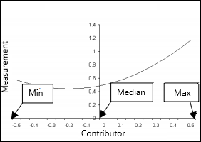
Table view |
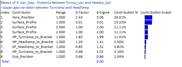
Histogram View
|
|
|
Contributor Analysis commands and features
Measure: Displays the measurement name from the model.
Index: The index number lists each contributor starting from 1. This can be changed in the Analysis Options under the Contributor Analysis settings.
Contributor: The name assigned to the GD&T in the model.
•Tolerance names that begin with "HP" indicate the contributor is the float between a pin and hole.
•Tolerance names that begin with "SP" indicate the contributor is the float between a pin and slot.
The description of the GD&T can also be shown. Showing the GD&T Description can be applied in the Contributor Analysis tab of the Display Options, which will be displayed under the Contributor Name.
Per Feature: Displays the individual coefficient for each point/feature in the given tolerance. The benefit of this mode is to highlight the individual point/feature with a high coefficient within the given tolerance.
Setting the Contributors to per Feature setting will display the Bonus information next to the feature name.
Feature Names |
Description |
SzFrm_CadSurf |
Size GD&T contributor on feature |
CadSurf1(SizeTol) |
Circle Size tolerance from coordinate point. |
CadSurf1(Bonus=+0.01) |
Displays the bonus from tolerances with |
CadSurf1(Form)(Orientation)(Location) |
Auto Refine: With Auto Refine active in the GD&T options dialog, the Form, Location and Orientation can be shown in the Contributor Features list, after the surface name. |
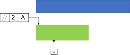
CadSurf1_HlmPt3_1 |
Form tolerance on a surface: displays the point node or Point name, and index in Contributor feature (HlmPt3 = Point Node; 1 = Index) |
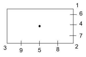
Orientation on a rectangular plane: display the node out of 9 nodes; used to measure the orientation on a plane. (ref. 71327) |
|
Pattern_Move_RT_A |
Pattern Move contributors shows the Translation (TR), with the direction (X,Y,Z), and Rotations (RT), shows the deviation type (A = Angle deviation) |
DRF_SEC |
When |
PtPair_1_1_1 |
Shown when points are used in GD&T: Straightness, Flatness, Circularity, Cylindricity, or Profile to No DRF, or Runout on a cone. PtPair: is the HLM index, a grouped set of points; "_1_1_1" is the point names. |
HLM Definitions
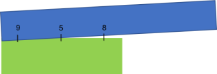
•CadSurf1_OrientPlane_9_5: Orientation on a rectangular plane: display the node out of 9 nodes; used to measure the orientation on a plane. (ref. 71327)
|
|
|
Plane example referenced in 3DCS: 3DCS will apply this grid of numbers on a planar feature. |
GD&T Example: Showing the applied orientation tolerance. |
Deviation/Visualize Effect: When shown through Visualize Effect, the node is shown where the deviation will occur from. For example: around Node 5. |
Per Tolerance: Combines all the individual point/feature coefficients of the given tolerance by a RSS. The benefit of this mode is to observe the combined coefficient of that tolerance while minimizing the rows in the Analyzer Matrix. Example: Contributor Per Tolerance - sqrt(feat1(tol1)^2+feat2(tol1)^2+...)
Range: Shows the input GD&T or tolerance range of the Contributor. Along with the units, a letter will indicate the type of tolerance.
•"M:" Indicates the Magnitude value of the tolerance. This is the linear magnitude, not the angle.
•"C:" Indicates the clearance of a hole and pin, or a pin and slot.
•"A:" Indicates the Angular range of the tolerance.
GeoFactor: Ratio of change in the Tolerance affecting the measure. The closer the G-Factor value is to zero, the lesser the tolerance variation for the measure.
6-Sigma: Displays the effective 6 Sigma value of the contributor. The 6 Sigma equals the Standard Deviation of the Range times the G Factor times 6. This is a simplified equation for linear tolerances, Positional/Circular Tolerances, Bonus, Hole and Pin float have a more complicated equation.
Sigma*G Factor*6 = Effective 6-Sigma
Position with Bonus equation: GeoFactor Range = GF*sqrt[(Pos+Bonus/2)^2+Bonus^2/36]
Estimated Worst Case Range (EWCR) = GeoFactor*Range
Critical Worst Case Range (CWCR) = Displays the effective worst case range of the contributor. The EWCR = EWCR(Contributor)/EWCR(Total).
Note: Depending on the display mode (Per Tolerance or Per Feature) and Bonus tolerance, the EWCR could show unexpected results. For best results, show the Contributor results with Per Feature mode set. If any Bonus tolerance exist, the EWCR result could be slightly higher.
Contribution: The percentage of a particular tolerance from amongst all the tolerances that contribute to the variation in a measurement.
Contribution Graph: This option will create a pseudo bar chart to graphically show the Percent Contribution of the given Contributor.