A ![]() Size GD&T is used to vary the size of a Feature of Size such as a hole, pin, slot, or tab.
Size GD&T is used to vary the size of a Feature of Size such as a hole, pin, slot, or tab.
Creating Size Procedure:
1.In the GD&Ts dialog, select ![]() Size in the drop-down list and select [Add GD&T]. This will open up the GD&T dialog.
Size in the drop-down list and select [Add GD&T]. This will open up the GD&T dialog.
2.Underneath the Features list, select [Add].
3.Select the feature(s) whose size should be varied by this GD&T.
4.Click [OK][Close] in the Pick FeatureSelect dialog
At this point the GD&T dialog will pop back up. Notice that the features selected are now in the Features list in the top half of the dialog.
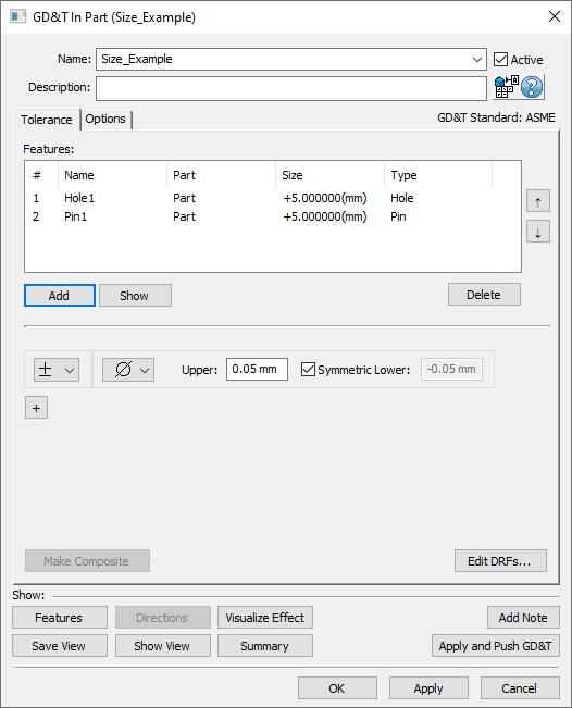
5.Select the zone type from the zone type drop down (linear zone, diametrical zone, or spherical zone).
6.In the Upper and Lower fields, enter the range for the GD&T. Note: if the tolerance is not symmetric, then the Symmetric checkbox must be deactivated to enable the Lower text entry field.
7.Select [OK] to exit the dialog and the save the GD&T.
How this GD&T Varies the Feature:
A ![]() Size GD&T will only vary the size of the feature, the location, orientation, and form of the feature will remain unchanged by this GD&T. This means that for slots/tabs the center plane will remain unaffected, for holes/pins the center axis will remain unaffected, and for spheres the center point will remain unaffected. The size of the feature will change uniformly across the entire feature. For example, the size of a pin on each build will change the same at any cross-section of the pin. To vary the sizes at individual cross sections see
Size GD&T will only vary the size of the feature, the location, orientation, and form of the feature will remain unchanged by this GD&T. This means that for slots/tabs the center plane will remain unaffected, for holes/pins the center axis will remain unaffected, and for spheres the center point will remain unaffected. The size of the feature will change uniformly across the entire feature. For example, the size of a pin on each build will change the same at any cross-section of the pin. To vary the sizes at individual cross sections see ![]() Circularity GD&T or
Circularity GD&T or ![]() Cylindricity GD&T.
Cylindricity GD&T.
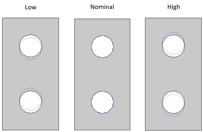
Some sample features with how a ![]() Size GD&T would commonly deviate them are shown below. Notice that the size of the 3DCS mesh is uniformly changing about the nominal geometry.
Size GD&T would commonly deviate them are shown below. Notice that the size of the 3DCS mesh is uniformly changing about the nominal geometry.
Note: While only a few deviated locations are shown below, the actual variations will use the entire specified zone.
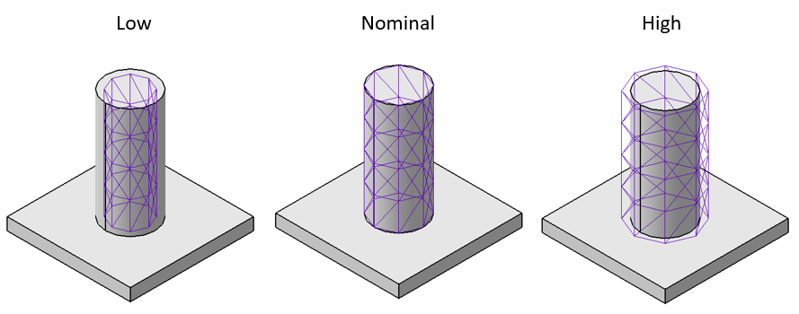
A pin at its low, nominal, and high sizes based on a bilateral Size GD&T.
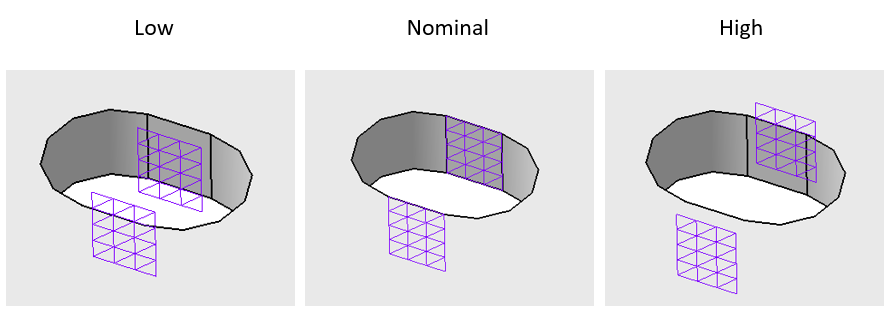
A slot at its low, nominal, and high sizes based on a bilateral Size GD&T.
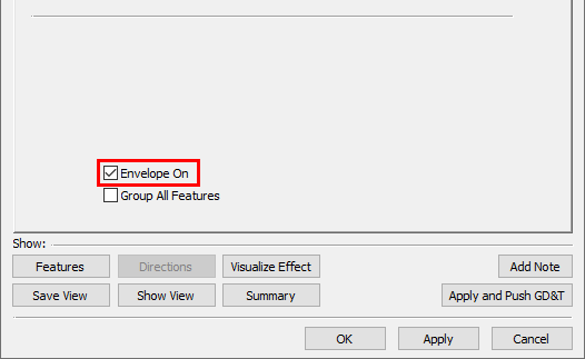
Envelope On/Off
The Envelope rule can either be applied or not for each ![]() Size GD&T by activating or deactivating the Envelope On checkbox in the Options tab. By default, this will be checked on for ASME and off for ISO but can be changed on a per GD&T basis. When the Envelope flag is activated, the form tolerance will be truncated with in the size tolerance range.
Size GD&T by activating or deactivating the Envelope On checkbox in the Options tab. By default, this will be checked on for ASME and off for ISO but can be changed on a per GD&T basis. When the Envelope flag is activated, the form tolerance will be truncated with in the size tolerance range.
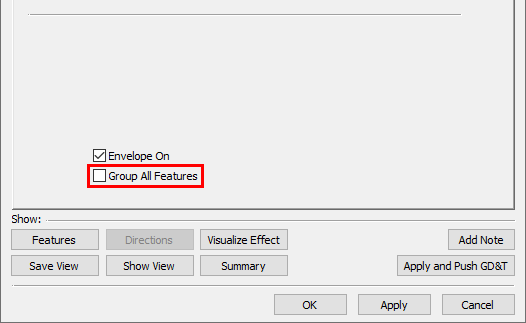
Selecting Multiple Features:
If multiple features are selected within the Features list of the GD&T dialog, each Feature will vary independently within the specified range. If desired, the features can vary as a group within the specified range by activating the Group All Features checkbox in the Options tab. By default this setting is turned off.
Size GD&T On Slots/Tabs:
A ![]() Size GD&T can be applied to a slot or tab in two different ways:
Size GD&T can be applied to a slot or tab in two different ways:
1.Creating a Slot/Tab using the Slots/Tabs function within 3DCS then adding that Slot/Tab to the Features list in the GD&T dialog.
2.Selecting the two faces of the Slot/Tab within the GD&T dialog.
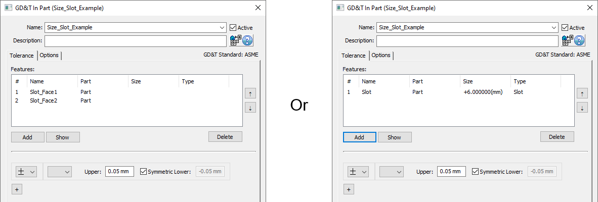
Either of these options will apply a Size GD&T to vary the size of the slot.
Linear Zone With Diametrical Features
If a ![]() Size GD&T with a linear zone is applied to a single diametrical feature (such as a hole or pin) then the diametrical size of the feature will vary, and the location of the feature will not vary.
Size GD&T with a linear zone is applied to a single diametrical feature (such as a hole or pin) then the diametrical size of the feature will vary, and the location of the feature will not vary.
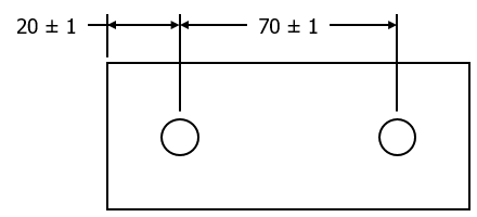
If a ![]() Size GD&T with a linear zone is applied to two diametrical features (within the same GD&T dialog), then the locations of the two features will vary relative to a center point between the two features. This can be used if two diametrical features make up a Datum such that the center point between them should remain unchanged, but the distance between the two features can vary. The example below shows the low, nominal, and high for one of these GD&T.
Size GD&T with a linear zone is applied to two diametrical features (within the same GD&T dialog), then the locations of the two features will vary relative to a center point between the two features. This can be used if two diametrical features make up a Datum such that the center point between them should remain unchanged, but the distance between the two features can vary. The example below shows the low, nominal, and high for one of these GD&T.
A pair of holes at its low, nominal, and high locations based on a bilateral linear Size GD&T.
It is not recommended to use a linear zone for a ![]() Size GD&T with three or more diametrical features.
Size GD&T with three or more diametrical features.
Size vs. Dimensioning Location
If there are several dimensions on a drawing that are locating features on a part (rather than GD&T determining location) then it is recommended that ![]() Dimensioning Location GD&T is used instead of
Dimensioning Location GD&T is used instead of ![]() Size GD&T.
Size GD&T. ![]() Size GD&T should only be used to vary the size of a Feature of Size. See Dimensioning Location for more information. The examples below show situations where
Size GD&T should only be used to vary the size of a Feature of Size. See Dimensioning Location for more information. The examples below show situations where ![]() Dimensioning Location should be used instead of
Dimensioning Location should be used instead of ![]() Size.
Size.
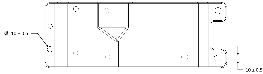
Dimensions are determining the locations of these faces.
Dimensions are determining the locations of these holes.