A ![]() Position GD&T is typically used to vary the location of a Feature of Size such as a hole, pin, slot, or tab. In accordance with ISO standards, it can also be used to vary the location of a planar surface. Note that even though in ASME or ISO a Position GD&T is controlling location, orientation, and form, in 3DCS it is only controlling location. For this reason, it may be necessary to add refinements to the GD&T that are not on the drawing.
Position GD&T is typically used to vary the location of a Feature of Size such as a hole, pin, slot, or tab. In accordance with ISO standards, it can also be used to vary the location of a planar surface. Note that even though in ASME or ISO a Position GD&T is controlling location, orientation, and form, in 3DCS it is only controlling location. For this reason, it may be necessary to add refinements to the GD&T that are not on the drawing.
Creating Position Procedure:
1.In the GD&Ts dialog, select ![]() Position in the drop-down list and select [Add GD&T]. This will open up the GD&T dialog.
Position in the drop-down list and select [Add GD&T]. This will open up the GD&T dialog.
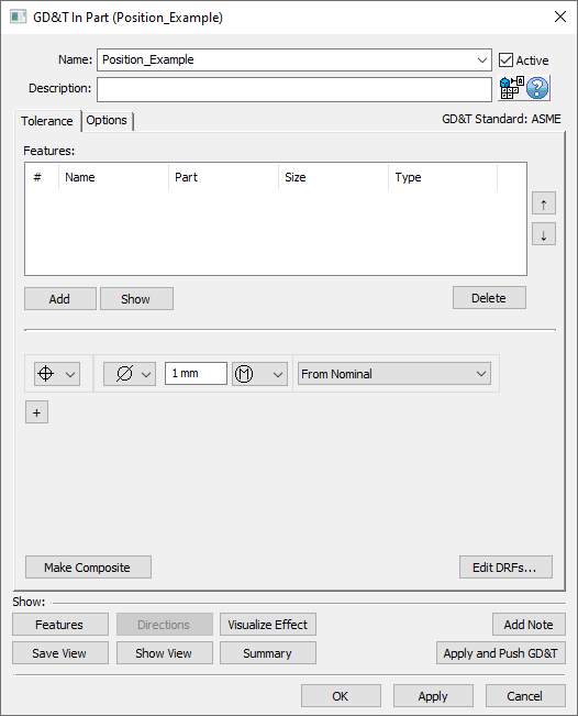
2.Underneath the Features list, select [Add].
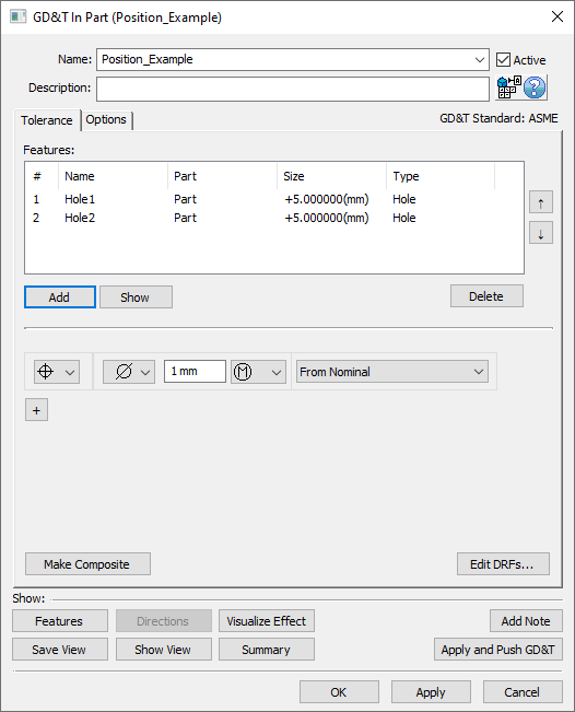
3.Select the feature(s) whose location should be varied by this GD&T.
4.Click [OK][Close] in the Pick FeatureSelect dialog
At this point the GD&T dialog will pop back up. Notice that the features selected are now in the Features list in the top half of the dialog.
5.Select the zone type from the zone type drop down (linear zone, diametrical zone, or spherical zone).
6.Enter the range in the text entry field.
7.Select the material modifier from the Material Modifier drop-down (blank for RFS, ![]() for MMC, or
for MMC, or ![]() for LMC).
for LMC).
8.Select No DRF, a DRF, or From Nominal from the Datum Reference Frame drop-down. See Datum Reference Frames for more information about creating and using DRFs.
9.Select [OK] to exit the dialog and the save the GD&T.
How this GD&T Varies the Feature - Diametrical Zone:
A ![]() Position GD&T with a diametrical zone is the most common use of the
Position GD&T with a diametrical zone is the most common use of the ![]() Position GD&T. The
Position GD&T. The ![]() Position GD&T only varies the location of the feature which means that the size, orientation, and form of the feature remain perfect. The location of the feature is varied within the specified diametrical zone.
Position GD&T only varies the location of the feature which means that the size, orientation, and form of the feature remain perfect. The location of the feature is varied within the specified diametrical zone.
A sample feature with how a ![]() Position GD&T with diametrical zone would commonly deviate them is shown below.
Position GD&T with diametrical zone would commonly deviate them is shown below.
Note: While only a few deviated locations are shown below, the actual variations will use the entire specified zone.
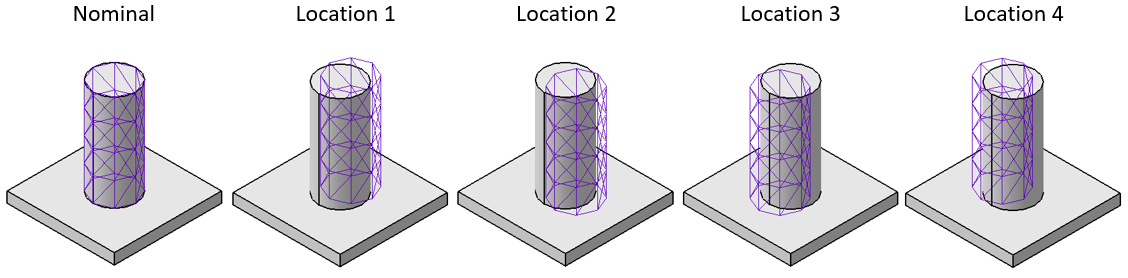
An isometric view of a pin with a Position GD&T.
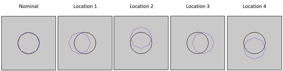
A top view of the same pin with a Position GD&T.
A diametrical zone will work for a Coordinate Point, axial feature, or spherical feature.
A diametrical zone will not work for planar or curved (non axial) surfaces.
How this GD&T Varies the Feature - Linear Zone:
A ![]() Position GD&T with a linear zone can be applied to a slot/tab, a planar surface, or a hole/pin. When applied to a slot/tab or a planar surface then the direction of variation for the linear zone is determined by the direction of the feature (the variation will be along the direction of the feature. When applied to a hole/pin the feature direction is not used and a custom direction may be required in the Options tab for 3DCS to determine the direction of variation. Depending on the DRF used, 3DCS may be able to automatically determine the direction of variation in this case but it is a best practice to deviate the model and check to see that 3DCS picked up the direction correctly. A direction can be added to the Options tab if the direction was not picked up correctly. See Custom Direction for more information.
Position GD&T with a linear zone can be applied to a slot/tab, a planar surface, or a hole/pin. When applied to a slot/tab or a planar surface then the direction of variation for the linear zone is determined by the direction of the feature (the variation will be along the direction of the feature. When applied to a hole/pin the feature direction is not used and a custom direction may be required in the Options tab for 3DCS to determine the direction of variation. Depending on the DRF used, 3DCS may be able to automatically determine the direction of variation in this case but it is a best practice to deviate the model and check to see that 3DCS picked up the direction correctly. A direction can be added to the Options tab if the direction was not picked up correctly. See Custom Direction for more information.
Sample features with how a ![]() Position GD&T with linear zone would commonly deviate them are shown below.
Position GD&T with linear zone would commonly deviate them are shown below.
Note: While only a few deviated locations are shown below, the actual variations will use the entire specified zone.
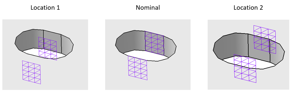
A slot with a Position GD&T with linear zone applied to it.
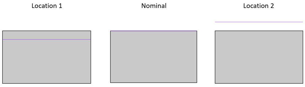
A planar surface with a Position GD&T with linear zone applied to it.
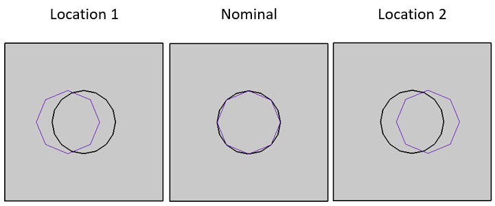
A hole with a Position GD&T with linear zone and custom direction applied to it. In this case the direction is in the left-right direction.
A linear zone will work for a Coordinate Point, planar feature, axial feature, or spherical feature.
A linear zone will not work for curved (non axial) surfaces.
How this GD&T Varies the Feature - Spherical Zone:
A ![]() Position GD&T with a spherical zone can be applied to a hole/pin, or a spherical feature. The zone that it will vary in is a spherical zone meaning that no direction will be required (as the zone is three dimensional).
Position GD&T with a spherical zone can be applied to a hole/pin, or a spherical feature. The zone that it will vary in is a spherical zone meaning that no direction will be required (as the zone is three dimensional).
A spherical zone will work for a Coordinate Point, axial feature, or spherical feature.
A spherical zone will not work for planar or curved (non axial) surfaces.
How this GD&T Varies the Feature - No DRF (73951):
A ![]() Position GD&T to No DRF can be applied to a hole or a pin. The zone that it will vary in is a diametrical zone, for the top and bottom features of a cylinder. Adding more Points to the axial feature will show each point deviating independently.
Position GD&T to No DRF can be applied to a hole or a pin. The zone that it will vary in is a diametrical zone, for the top and bottom features of a cylinder. Adding more Points to the axial feature will show each point deviating independently.
The No DRF option will work with a series of Coordinate Points with a Diameter along a line or axial feature.
The No DRF option will not work for planar or curved surfaces.
Applying Maximum Material Condition (MMC) or Least Material Condition (LMC) for Bonus:
Material Modifiers are allowed for a ![]() Position GD&T for a feature that also has a
Position GD&T for a feature that also has a ![]() Size GD&T. 3DCS will give an error if
Size GD&T. 3DCS will give an error if ![]() for MMC, or
for MMC, or ![]() for LMC are present in the Material Modifiers drop-down for a feature that does not also have size variation. For more information on Bonus Tolerance see Bonus Tolerance.
for LMC are present in the Material Modifiers drop-down for a feature that does not also have size variation. For more information on Bonus Tolerance see Bonus Tolerance.
Composite Position GD&T:
Composite GD&T for ![]() Position GD&T can be created within 3DCS to be applied to a pattern of pins or holes, for example. See Composite GD&T for more information.
Position GD&T can be created within 3DCS to be applied to a pattern of pins or holes, for example. See Composite GD&T for more information.
Adding a Projected Tolerance Zone:
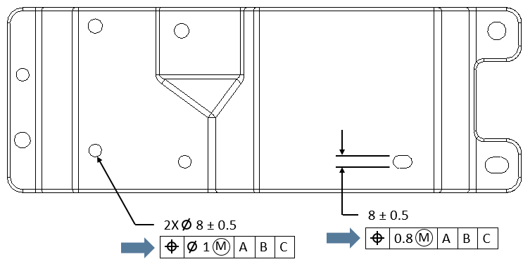
On the drawing there may be a Projected Tolerance Zone that is associated with the ![]() Position GD&T like the one shown on the note below. If this is the case then the user can set the Projected Tolerance Zone length in the Projected Tolerance Zone field of the Options tab. By default the Projected Tolerance Zone is 0 which means it is off. The default direction of the Projected Tolerance Zone is based on the feature direction assigned by 3DCS to the hole selected. This direction is often an arbitrary direction, so if the Projected Tolerance Zone should be applied in the opposite direction of the 3DCS assigned direction, the user can simply activate the Switch Project Direction checkbox to flip the direction used for the Projected Tolerance Zone. Note: While it is common to see the Projected Tolerance Zone applied to a
Position GD&T like the one shown on the note below. If this is the case then the user can set the Projected Tolerance Zone length in the Projected Tolerance Zone field of the Options tab. By default the Projected Tolerance Zone is 0 which means it is off. The default direction of the Projected Tolerance Zone is based on the feature direction assigned by 3DCS to the hole selected. This direction is often an arbitrary direction, so if the Projected Tolerance Zone should be applied in the opposite direction of the 3DCS assigned direction, the user can simply activate the Switch Project Direction checkbox to flip the direction used for the Projected Tolerance Zone. Note: While it is common to see the Projected Tolerance Zone applied to a ![]() Position GD&T on a drawing, because 3DCS uses Position as only a location tolerance, the Projected Tolerance Zone will have no influence on the results. It is recommended that an orientation refinement is also applied to the
Position GD&T on a drawing, because 3DCS uses Position as only a location tolerance, the Projected Tolerance Zone will have no influence on the results. It is recommended that an orientation refinement is also applied to the ![]() Position GD&T (such as
Position GD&T (such as ![]() Perpendicularity,
Perpendicularity, ![]() Angularity, or
Angularity, or ![]() Parallelism) and the Projected Tolerance Zone is also applied to that.
Parallelism) and the Projected Tolerance Zone is also applied to that.
![]()
This is an example of a callout that has a Projected Tolerance Zone. In this case, the zone is of length 50 so that is what would be entered into the Options tab.
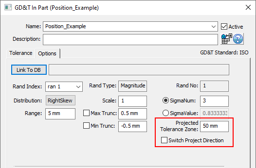
This is where a Projected Tolerance Zone can be added to the Options tab of the GD&T dialog.
Best Practices:
Applying Common Zone to Location, Orientation and Form: This is the details and process to applying Common Zone (CZ) to a Position tolerance, and to apply refinements to the same feature. This is intended for Position on a planar feature and in the ISO standard.
•If you want CZ for Location - Do nothing. By varying relative to the same DRF or From Nominal, the Features in the list will inherently vary within the same zone!
•If you want CZ for Orientation (and presumably Location) then add Group All Features to the Location call-out and leave it turned off for the Orientation. This will vary the Orientation Zones together relative to the DRF but the individual Features will be allowed to vary independently of each other within that Orientation Zone.
•If you want CZ for Form (and presumably Location & Orientation) then Group All Features would need to be toggled on for Location & Orientation and turned off for Form.