The
Unlike the Six-Plane move, the Step Plane uses only one direction to orient the primary planes, one direction to orient the secondary plane, and one for the tertiary. These are defined in the Direction part of the Step Plane dialog box. Because there are only three and not six directions to be concerned with (as in the Six Plane Move), modeling with the Step Plane move is easier.
Although there is only one direction to define the primary plane, it does not mean that the three primary locating points must be coplanar. The locating planes are parallel but may be stepped (parallel but offset a certain distance) relative to each other. Hence the name "Step Plane".
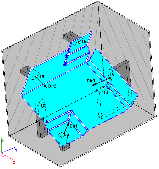
The Step Plane move locates an object to a target with six points and six planes (three primary, two secondary, and one tertiary). The Step Plane dialog box only allows three directions to be entered. Direction one (Dir#1) orients the first three primary planes. The second direction defines the orientation of planes four and five. The third direction orients plane six. At the completion of the move, each point will lie on its corresponding plane.
|
|
See Also...
|
Example Model: C:\Users\Public\Documents\DCS\3DCS_V5_8_2_0_0\3DCS CAD & Example Models\Reference Models\Moves\Step Plane move
|
Specifications:
Object points: O1, O2, O3, O4, O5, O6
Target points: T1, T2, T3, T4, T5, T6
Directions: Dir1, Dir2, Dir3
Object/Target Plane: Dir1, Dir2, Dir3
The three primary planes contain either O1, O2, and O3, or T1, T2, and T3 respectively, and have Dir1 as their normal vector. Likewise, the two secondary planes contain either O4 and O5, or T4 and T5 respectively, and have Dir2 as their normal vector. This leaves either O6 or T6 and Dir3 to define the tertiary plane.
The Step Plane move has traditionally only moved object points to target planes. The Step Plane move can now also move object planes to target points. For most design scenarios, the locating planes may be placed on the target. However, the locating plane should be placed on the object when:
•The move uses a pin and slot pair and the slot is on the object
•When it is easier to obtain an object plane vector than a target plane vector.
The user runs the risk of introducing interference problems and inaccurate results when planes are defined improperly.
Procedure:
•Select the parts to move.
•Select the six Object and Target points in sequence.
•Open the "Dir. Index" drop-down list to define the three direction vectors. The vectors are all initially set to (0,0,1).
•Specify each direction vector as defining either an object or a target plane.
•Each active direction vector can be defined with any of the available methods in the "Dir. Type" drop-down list. If AssocDir is selected for Dir1, the direction will be the vector associated with T1 or O1 if Object Plane is selected. If AssocDir is selected for Dir2, the direction will be the vector associated with T4 or O4 if Object Plane is selected. If AssocDir is selected for Dir3 , the direction will be the vector associated with T6 or O6 if Object Plane is selected.
•After setting the direction for the primary plane, click on the "Dir 1" window or the drop-down arrow to the right of the drop-down box. From the drop-down list, select "Dir 2" and "Dir 3" in turn to define those vector directions.
•If the primary direction vector type is Default, the direction will be defined normal to the plane through the three primary target points. In this case there is no primary step.
•If the secondary direction type vector is Default, the direction will be defined (after the primary direction has been established) by a plane through the two secondary points that is normal to the primary direction. In this case there is no secondary step.
•If the tertiary direction vector type is Default, the direction will be defined (after the primary and secondary directions have been established) as normal to the primary and secondary directions.
•Select "OK" to exit the Step Plane menu.
Step Plane Move Logic:
The object is translated or rotated to locate each successive object point or plane on its corresponding target plane or point. As each point or plane is located a degree of freedom is constrained, until the object is completely positioned. If the move is ill-defined, and therefore cannot be completed, the object will be returned to its position prior to the move.
The strategic value of the Step Plane Move is that its logic corresponds to many actual assembly processes. After the primary points (or planes) are located, the object can slide and rotate on the primary stepped locators to a position that allows the secondary points (or planes) to be located. Then the object slides on both the primary and secondary stepped locators until the tertiary point (or plane) is located.
If the move is ill-defined so that some degree of freedom is either under or over constrained then the move will only complete those steps that are properly defined. At times, it can be difficult to recognize why a move might be ill-defined, for this reason, the user should include measurements in the model to verify that the move is working correctly. An ill-defined move typically indicates either an error in the model or flaw in the design.
The Step Plane move is well suited to many applications because the primary, secondary and tertiary directions need not be mutually perpendicular. If the parallelism requirement for the primary or secondary planes stated above is not reasonably met, the Six-Plane move should be considered instead. When using the move with contoured surfaces, the user must bear in mind that the move approximates each contact region as a plane with the specified normal vector.