The
The Six-Plane move does not require that the six planes be clearly defined as primary, secondary, and tertiary planes as does the Step-Plane move. An example of this scenario is when a keyed shaft is located in a V-Block fixture (shown below). The Six-Plane move is a good choice for locating parts that do not have purely perpendicular primary secondary and tertiary planes.
|
|
See Also...
|
Example Model:C:\Users\Public\Documents\DCS\3DCS_V5_8_2_0_0\3DCS CAD & Example Models\Reference Models\Moves\Six Plane move |
Specification:
| Object points | O1, O2, O3, O4, O5, O6 |
| Target points | T1, T2, T3, T4, T5, T6 |
| Directions | Dir1, Dir2, Dir3, Dir4, Dir5, Dir6 |
Each object or target plane is defined by a point and the corresponding direction vector. While any point on each plane is sufficient to define the plane, it is recommended that each point be chosen so that it nominally corresponds to the point with which it is paired, if possible.
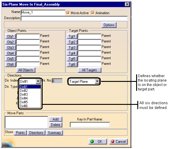
Procedure:
1.Select the parts to move.
2.Select the six object and target points in sequence.
3.Open the "Dir. Index" drop-down list to define the six direction vectors. The vectors are all initially set to (0,0,1).
4.Specify each direction vector as defining either an object or a target plane. All six direction vectors must be defined and active.
5.Each direction vector can be defined with any of the available methods in the "Dir. Type" drop-down list. If AssocDir is selected, the direction will be the vector associated with the object or target point in the corresponding position of that list.
6.After setting the direction for the first plane, click on the "Dir#1" window or the down arrow to the right. From the drop-down list, select the other direction labels (Dir#2, Dir#3,…) in turn to define those vector directions.
7.Select "Options" to define any bends or hole/pin floating.
8.Select "OK" or "Finish" to exit the Six Plane menu.
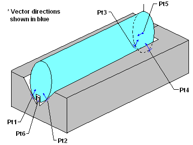
Figure 1: Keyed shaft located in V-block using Six-Plane move.
The Six-Plane move locates an object to a target by matching six points on the object part to six planes on the target part. The Six-Plane move also has the ability to define some or all of the locating planes on the object part rather than the target part. Since a plane is defined by a point and a direction, the locating plane will be on the target or object depending on where the direction is defined.
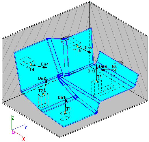
Figure 2: Locating a part with non-perpendicular primary, Secondary, and Tertiary planes.
For most design scenarios, the locating planes may be placed on the target. However, the locating plane should be placed on the object when:
•The move uses a pin and slot pair and the slot is on the object. Make the Object the plane for only the slot and pin points and not all the points which locate the part
•When it is easier to obtain an object plane vector than a target plane vector.
•The user runs the risk of introducing interference problems and inaccurate results when planes are defined improperly.
If the move is ill-defined so that some degree of freedom is either under or over constrained, then the move cannot be completed and the object will be returned to its position prior to the move. At times it can be difficult to recognize why a move might be ill-defined. For this reason the user should include measurements in the model to verify that the move is working correctly. An ill-defined move typically indicates either an error in the model or a flaw in the design.