The purpose of
|
Inputs
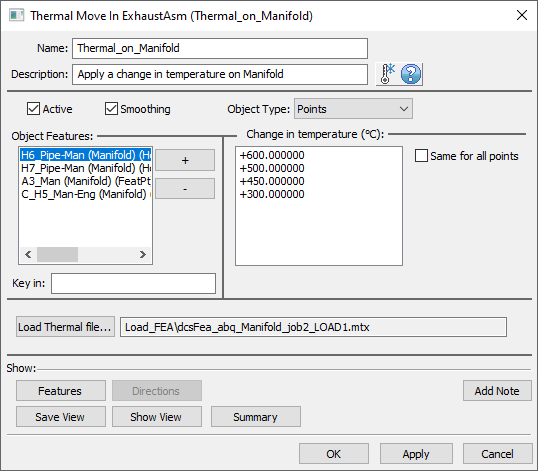
An example of the Temperature Move dialog is show here:

•Name: The move name must be unique to the model.
•Description: This is an optional explanation of what the move does.
•Help: The Help button is context sensitive; it will open the Help Manual at required topic page.
•Activate Smoothing to deform the entire part.
•Object Type: Offers two options:
oPart - Select a part to apply the thermal deformation to the entire part.
oPoints - Select a set of points to apply the thermal deformation. The other points on the part will be indirectly affected (if linked to a mesh node). The points can be added/removed using 'plus' and 'minus' buttons. The number of points can be from 1 to n.
oChange in Temperature (C): Value, in Celsius degrees, by which the temperature is changed. If applied on the entire part one temperature value will be used.
This input indicates the temperature change, therefore it depends on the initial condition in the FEA mesh file. If an initial condition does not exist in the mesh file it means that the initial temperature is absolute zero.
If an initial condition has been set, let's say 20 degrees C temperature field, then your input for the 'Change in Temperature' should be 140 C to reach a final temperature of 160 C.
•Same for all points: This option is available only when applying temperature change on individual points. By checking this box the same value is applied to all points in the Object Features list. If the box is left unchecked the user needs to input a separate value for each point.
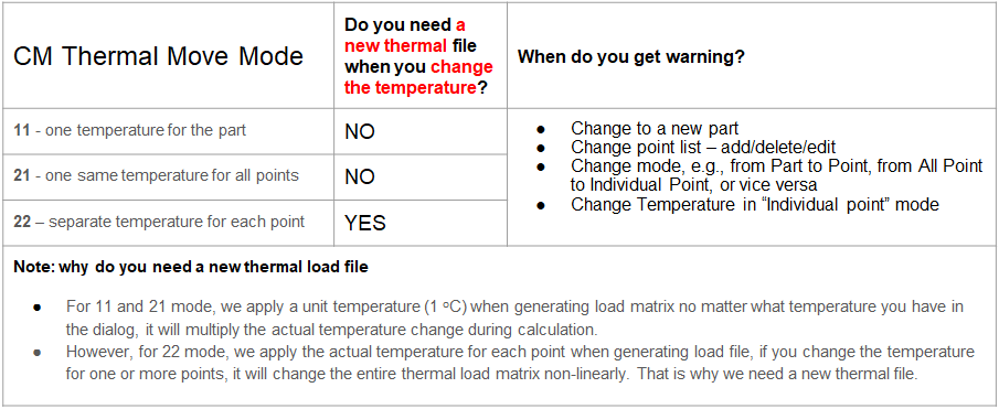
•Load Thermal file...: The user will click this button to add the Thermal Load file created with StiffGen. The table below explains when a new Thermal Load file is needed.

•Summary:Shows move information in Notepad.
•Features: Shows the Object Features in the Graph Window.
Outputs
•The result of this routine will be the deformed object part based on the Thermal Load file.
•This is a permanent deformation which propagates to other feature points on the object part.
Process
•Select the Thermal Move icon ![]() and select the part to create the move in. This move must be at a product level, at least one level above the part, after the Load FEA Data move.
and select the part to create the move in. This move must be at a product level, at least one level above the part, after the Load FEA Data move.
•Add part or object points using the 'plus' button.
•Add the temperature value(s).
•Click OK to save and close the dialog.
•Open StiffGen, add the part for whic the Thermal Move was created, select appropriate FEA Tool and check the Thermal load box to generate the Thermal Load file. Generate thermal load file.Close StiffGen.
•Return to Thermal Move and upload the Thermal Load file you just created.
•Use the Features button to display the points on the screen to verify the object points are selected correct.
Notes
•Nominal Build must be performed before this move is executed.
•Thermal move validation messages will be triggered by the 'Validate MTM on dialog close' setting in Preferences and shown in Validate window.
•If a change of temperature values is needed the Thermal Load file has to be regenerated if each point has its own temperature value. If the same temperature change is applied to all points, no Thermal Load file regeneration is necessary.
•It is recommended to always generate a 6dof thermal load file for shell mesh while for solid mesh you can only create 3dof thermal load file.
Validation Messages
•If a different thermal move than the one for which the Thermal Load file was generated is active, no thermal deformation will apply to the part and the following messages will be issued in the Run Log:
oPart Name...Move Name... Object Features in dialog are not consistent with those in Thermal Load File: FEA points diff temp\..._LOAD1.mtx
oPart Name...Move Name... Thermal Move Settings are inconsistent with Thermal Load File - FEA points diff temp