The purpose of
|
This move requires a mesh file and stiffness matrix loaded for the object part.
Process
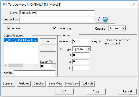
•Select![]() Torque and choose the part or assembly for the move to be created in the tree. This move must be at a product level, at least one level above the part.
Torque and choose the part or assembly for the move to be created in the tree. This move must be at a product level, at least one level above the part.
•Add or Remove points using the plus ![]() and minus
and minus ![]() buttons.
buttons.
•Check "Same direction based on the first object" if all points have the same direction.
•Use the [Features] button to display the points on the screen and verify if their location and direction are correct.

 About
About
•Name: The move name must be unique to the model. •Description: This is an optional explanation of what the move does. •Help: The Help button is context sensitive; it will open the Help Manual at required topic page. •Activate Smoothing to deform the entire part. •Options: 1.When a measure is added in the Options as a Condition will trigger the move when the selected measure is within the specified limits. 2.When a measure is added in the Options as a Condition and the "Execute if out of specified limits" is checked will trigger the move when the selected measure is outside the specified limits.
•Object Features: These are the points where the torque will be applied. The number of points can be from 1 to n. •Amount: This is the torque value applied to each point in [N*m]. •Dir. Type: Allows to change the vector direction for the each point, similar to the direction options available in the other MTMs: Type In, Two Pt, Normal, AssocDir (picks up the associated direction of the Target point), and TwoPtDir.
|
|---|
