The
|
Parameters: Checking the largest Pin or the smallest Hole
Geometry: Two or more Coordinate points with Circles Size tolerances set as holes or pins or Feature Points as Features of Size.
Specification Limits (Spec. Limits):
•Hole option: Largest value in the Upper Spec Limit
•Pin option: Smallest value in the Lower Spec Limit
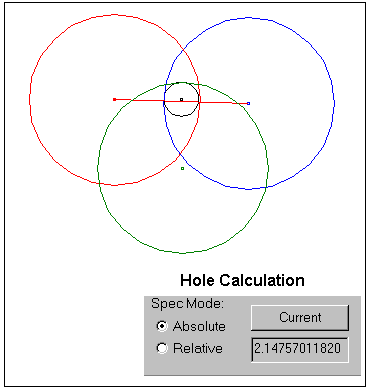
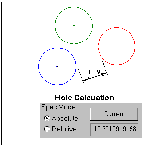
Spec Mode: Absolute
Direction: Required - Can set to Associative if using Pin/Hole feature (Direction based on Least Squares Axis routine is recommended)
Analysis Settings: Show the Min, Max and Range output to determine the Largest Pin (Min) and Smallest Hole (Max)
Modes:
This measurement provides 3 basic calculation modes:
Auto: The Hole or Pin options will be determined by the Features or Coordinate Points with circle size tolerances used in the measure.
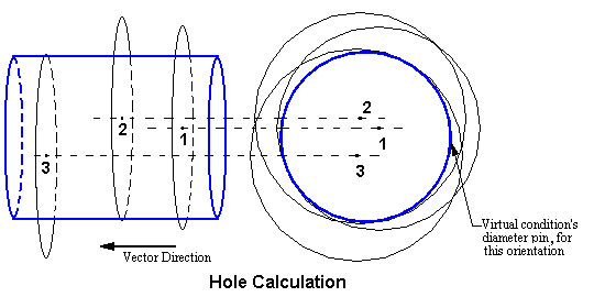
•Hole Option: Measures two or more circular holes in a specific direction. The output is the largest diameter pin; the axis is the direction vector that simultaneously fits inside all of the circular holes.
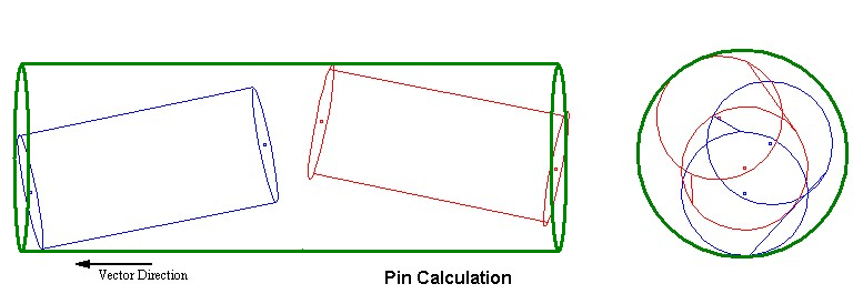
•Pin Option: Measures two or more circular pins in a specific direction. The output is the smallest diameter tube; axis is the direction vector that simultaneously fits outside all of the circular holes.
Inner Diameter: Measures two or more circular holes and or pins in a specific direction. The output is the largest diameter pin; the axis is the direction vector that simultaneously fits inside all of the circular holes and or pins.
Outer Diameter: Measures two or more circular holes and or pins in a specific direction. The output is the smallest diameter tube, whose axis is the direction vector that simultaneously fits outside all of the circular holes and or pins.
Output:
The vector direction is normal to the surface the holes are in. Only one vector can be used to define all of the circles. The vector used is the vector defined in the Virtual Clearance Measurement, not the vector used to define the circles.
Negative reported values indicate the minimum amount each diameter would have to increase, for actual overlap to occur.
Notes:•For best results, users can apply •All holes are assumed to have perfect form, coplanar and normal to the direction vector. The diameter used is the active diameter associated with the input points. •This measure may produce incorrect Contributor Analysis or GeoFactor Equation-Based results, see Analysis Comparison & Assumptions.
|