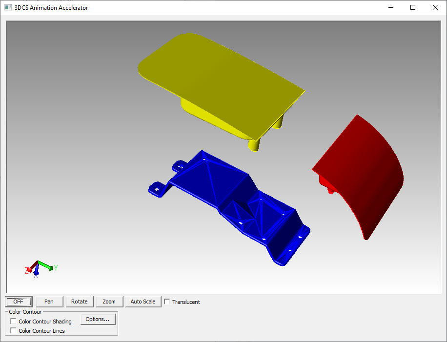
This function will display the parts and the 3DCS data in a lightweight graphics window. Functions in the toolbar can be used to manipulate the graphics window.
The Animation Accelerator will require a license to open. Please contact your DCS representative to learn more. |
See also |
Procedure:
1.Select the ![]() Animation window icon under the Model Navigator Icon to launch the Animation Window.
Animation window icon under the Model Navigator Icon to launch the Animation Window.
2.The Animation window opens up with all the CAD files of the opened model, in to a light weight CAD and displayed in a light weight graphics window.
3.This Animation window is linked with the 3DCS Ribbon, doing all the Graphic Analysis functions (Nominal Build, Separate, Deviate and Animation) will reflect the model in the Animation window as well.
Animation Window Functions:
Startup Driver: DirectX or OpenGL. DirectX is currently less likely to be installed or supported on most Windows desktops or laptops. Switching to OpenGL will switch the Animation Accelerator's driver.
Switching the driver will require the user to close and reopen the dialog for the new driver to be used. |
Pan: Click this Icon and use left button mouse and drag.
Rotate: Click this Icon and use left button mouse and drag.
Zoom: Click this Icon and use left mouse button to move up and down to see Zoom Out and Zoom In.
Auto Scale: Click this icon to instantly fit the Model to the Screen.
Off: Turns off all Graphic Manipulation.
Color Contour: Color Contour is a visualization tool which will show the level of variation on parts during Deviation and Simulation. It allows a user to highlight part and assembly tolerances, and measurements that are most critical to the assembly process. For Color Contour functions and options, please see the Color Contour page.
Translucent: Makes the CAD display Translucent within the Animation Accelerator window.
Other functions:
Reframe On: While the Animation Accelerator window is open, users can use the right-click functions within the Model Navigator or the Analysis Summary window and Reframe On will Zoom to the selected point or feature. The Reframe On function within the Analysis Summary/Window will also zoom to the selected feature or Tolerance in the Animation Accelerator.
When to use the Animation Accelerator?
1.Large Model deviation: The Animation Accelerator converts the CAD into a light weight CAD file and displays in a light weight graphics window, allowing ![]() Nominal Build,
Nominal Build, ![]() Separate, Deviate, and
Separate, Deviate, and ![]() Animate to perform faster than displayed in the NX graphics window.
Animate to perform faster than displayed in the NX graphics window.
2.Using Color Mapping functions: Once you select the Color Contour Shading option, 3DCS will ask if all parts can be set to show Color Contour. Users can specify which parts or sub-assemblies to show Color Contour shading by going to MTM On/Off. Each part also has an option to activate/deactivate Color Contour by going to Edit Part dialog.
Notes:•Animation Accelerator window will hide the parts that is hidden in the Tree. (73687)
|