Color Contour is a visualization tool which will show the level of variation on parts during Deviation and Simulation. It allows a user to highlight part and assembly tolerances, and measurements that are most critical to the assembly process.The Color Contour tools can be found in the Display toolbar.
Topics: |
Color Contour |
||
|
|
|
 Hide/Show Color Contour Shading: This function activates color mapping on parts in the graph window.
 Hide/Show Color Contour Lines: This function activates color map lines that represent statistical data for active measurements.
 Color Contour Options: This function allows user to configure settings for color mapping feature. See below for the preferences.
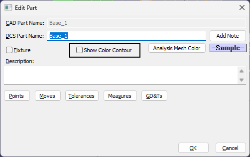
Activating/Deactivating Color Contour for Parts or sub-assemblies:
Edit Part dialog: double-click a part in the Model Navigator. Select the option to Show Color Contour
|
|
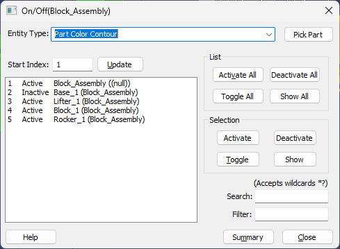
Use the On/Off or Global On/Off dialog to hide/show Color Contour per parts or sub-assemblies. |
|
Notes:•Using Materials on parts is a good way to show actual parts geometry to be used in a 3DCS Report. The Materials prevents Color Contour from showing, so to use Color Contour, please Hide the Materials that are applied to the parts. |