This routine will move a pair of holes to a similarly sized and Toleranced holes. This DLL contains 2 sets of the User Routines:The first set of routines controls all six degrees of freedom. The second set only controls the tertiary direction (and has a "2" appended to the end of their names).
|
Example Models:C:\Users\Public\Documents\DCS\3DCS_V5_8_2_0_0\3DCS CAD & Example Models\Reference Models\Moves\Axis Align - Hole to Hole
Within this Section:There are ten different routines for this module - dcu_cr2cr.dll: The 1st Set Routines: •Cr2CrCentered (Cr2CrCentered) •Cr2CrFastener (Cr2CrFastener) •Cr2CrAxisAlign (Cr2CrAxisAlign) •Cr2CrDynMidPt (Cr2CrDynMidPt) •Cr2CrFastenerInch (Cr2CrFastenerInch) The 2nd Set Routines: •Cr2CrCentered2 (dcsMvCr2CrCentered2) •Cr2CrFastener2 (dcsMvCr2CrFastener2) •Cr2CrAxisAlign2 (dcsMvCr2CrAxisAlign2) •Cr2CrDynMidPt2 (dcsMvCr2CrDynMidPt2) •Cr2CrFastenerInch2 (Cr2CrFastenerInch2) |
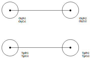
Required Inputs: Object Features: 2 Object Points (objPt1, objPt2) associated with circles (objCr1, objCr2). The hole centers can be defined as the Object points. Target Feature: 2 Target Points (tgtPt1, tgtPt2) associated with circles (tgtCr1, tgtCr2). Hole centers can be defined as the Target points.
Directions List: One direction is optional for controlling primary plane direction. Enter a 1 in the Dir. No. field. Define the direction perpendicular to the target primary plane. Component List: At least one component is required. The parts listed in this section will be transformed based on the routine selected. Value List: With the Fastener routines only: use the Values... button to simulate a fastener (pin) diameter as a Constant. Hole Pin Floating: Available in the Options dialog. The float will be deactivated on creation by default.
|
|---|
The location of the object is based on hole position and size variation. The variation of the two hole pairs is spread evenly between the two hole pairs. This routine is used when the relative size between the hole and a temporary fastener is small. The expanding pin would evenly distribute the variation due to the hole size and location. No fastener size is required. (If a fastener size is declared, the software will indicate a no build situation.)
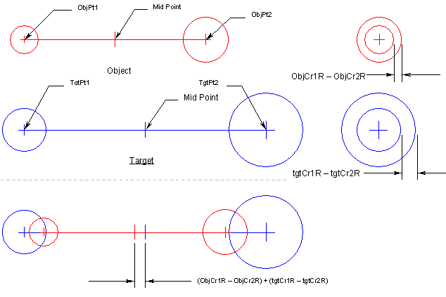
Procedure1.mvObjPt1 = (objPt1 + objPt2)/2; mvTgtPt1 = (tgtPt1 + tgtPt2)/2 2.XD = [(objCr1R – objCr2R) + (tgtCr1R – tgtCr2R)]/2 3.Apply XD to mvTgtPt1 4.mvObjPt2 = objPt1; mvTgtPt2 = tgtPt1. 5.mvObjPt3 = calObjPt3; mvTgtPt3 = calTgtPt3. 6.Apply 3-Point Move.
|
|---|
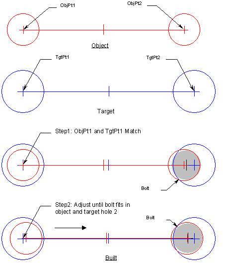
The object is located by the first pair of holes then shifted, if necessary, so that the fastener will fit in the second pair of holes. The object is varied in relation to the target based on the two pair of holes being moved relative to each other without violating a fastener size. This is used when the relative hole to fastener size is large and there may be movement between the object and target in actual application. The fastener is a constant value which is put into the 'More' section of the DLL.
Procedure:1.mvObjPt1 = objPt1; mvTgtPt1 = tgtPt1. 2.mvObjPt2 = objPt2; mvTgtPt2 = tgtPt2. 3.mvObjPt3 = calObjPt3; mvTgtPt3 = calTgtPt3. 4.Apply 3-Point Move. 5.adjust {objPt2, tgtPt2} relative to fastener size diff = |tgtCr2R – objCr2R| - |tgtPt2 – objPt2|
|
|---|
3. Cr2CrAxisAlign (Cr2CrAxisAlign): "first-axis-alignment"
The first pair of holes selected will be aligned and the second pair is rotated to align. This will distribute the variation to the second pair of holes. No fastener size is required. Use of this mode generally does not impact the Sensitivity and GeoFactor results, see the Analysis Comparison & Assumptions and Linearity sections for more information.
Example Model: ..\example_models\solid_examples\moves\hole2hole\AxisAlign.wtx
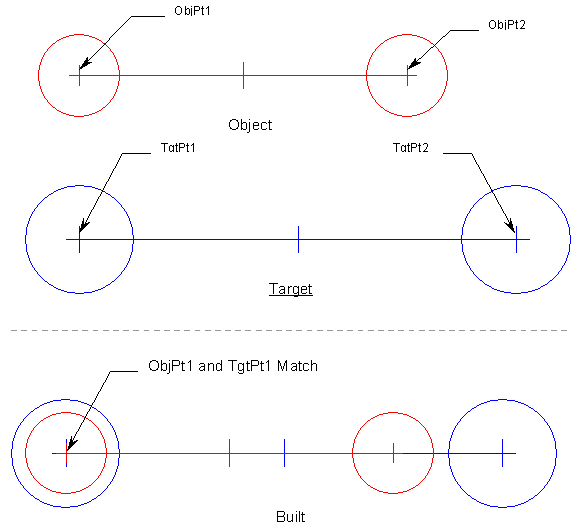
Cr2CrAxisAlign: first-axis-alignment
1. mvObjPt1 = objPt1; mvTgtPt1 = tgtPt1.
2. mvObjPt2 = objPt2; mvTgtPt2 = tgtPt2.
3. mvObjPt3 = calObjPt3; mvTgtPt3 = calTgtPt3.
4. Apply 3-Point Move.
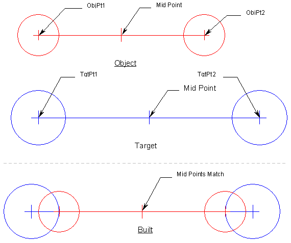
4. Cr2CrDynMidPt (Cr2CrDynMidPt): "dynamic middle points"
The object is located to the target by the mid point between the object holes being moved to the mid point between the target holes and object point 2 is aligned with target point 2.
The variation is spread between the object and target hole pairs. No fastener size is required. Use of this mode generally does not impact the Sensitivity and GeoFactor results, see the Analysis Comparison & Assumptions and Linearity sections for more information.
Example Model: ..\example_models\solid_examples\moves\hole2hole\Dynamic.wtx
Cr2CrDynMidPt: Dynamic Middle Points
1. mvObjPt1 = (objPt1 + objPt2)/2; mvTgtPt1 = (tgtPt1 + tgtPt2)/2
2. mvObjPt2 = objPt1; mvTgtPt2 = tgtPt1.
3. mvObjPt3 = calObjPt3; mvTgtPt3 = calTgtPt3.
4. Apply 3-Point Move.
5. Fastener Dependent (Inch)
The Cr2CrFastenerInch routine produces the same result as Cr2CrFastener except requiring that the fastener size is in Inches instead of in mm. New in 3.12.1 Please note use of this mode can impact the Sensitivity and GeoFactor results, see the Analysis Comparison & Assumptions and Linearity sections for more information.
The 2nd Set Routines:
6. Cr2CrCentered2 (dcsMvCr2CrCentered2)
7. Cr2CrFastener2 (dcsMvCr2CrFastener2)
8. Cr2CrAxisAlign2 (dcsMvCr2CrAxisAlign2)
9. Cr2CrDynMidPt2 (dcsMvCr2CrDynMidPt2)
10. Cr2CrFastenerInch2 (Cr2CrFastenerInch2)
Calculation
Assume the previous move (assembly method) will align object points with targets. These routines will modify the center point location on a calculation plane specified by the first direction. If the first direction is not available, the associated direction for the first target point will be used as the calculation plane. These routines will not change the primary plane orientation because the routines only perform one translation (sliding) along cr2cr axis on the specified primary plane. This behavior is similar to Pattern Move.
Note: The translation is only controlling the tertiary plane. The primary plane is the specified plane; and the secondary plane is determined by the primary plane and two target centers.