In either the One Point or Two Point option, the Dynamic Point cannot be varied by placing it within a tolerance. Its variation is entirely dependent on the variation of its Control Point(s).
The Control Points for a Dynamic Point may be in different parts, however, Dynamic Points are automatically created in the same part as the first Control Point (Control Pt1 in the dialog). This means that the Dynamic Point and one Control Point may be placed in separate sub-assemblies. If this is the case, when the sub-assemblies are opened separately the analysis results may be inaccurate.
|
Creating a Dynamic Point:
1.Select ![]() Dynamic Point on the 3DCS Model Creation Toolbar or navigate to it in the 3DCS drop-down list (Features -> Dynamic Point) to open the Dynamic Point dialog.
Dynamic Point on the 3DCS Model Creation Toolbar or navigate to it in the 3DCS drop-down list (Features -> Dynamic Point) to open the Dynamic Point dialog.
2.Select [Create].
3.Determine if the Dynamic Point is to be based on One or Two Control Points:
•One Control Point method: Used when it is necessary to duplicate the exact same variation of a point projected a linear distance along the associated vector of that Control Point. The Dynamic Scale field becomes the actual distance from the Control Point in the units set by the CAD software's options.
1. Select the Control Point from the Graphics Window.
2. Select [Close] from the Pick Point dialog or select the first Control Point again.
3. In the Dynamic Scale field, set the linear distance (positive or negative). The Dynamic Point will be offset along the associated vector of the Control Point.
4. In the Dynamic Pt Name input field, change the Dynamic Point's name if desired.
5. Select [Apply] and verify the point location in the Graphics Window.
6. Make updates if necessary and [Apply] changes.
7. Select [OK] to close the dialog.
•Two Control Point method: Used when it is necessary to create a point that is always a multiple of the distance between two varying Control Points. If this multiple is 0.5, the Dynamic point will be placed at the average of the two Control Points.
1. Select the first and second Control Point from the Graphics Window.
2. In the Dynamic Scale field, set the multiple of the distance between the two Control Points. A Dynamic Scale of 0.0 places the Dynamic Point on Control Pt 1 and a Dynamic Scale of 1.0 places it on Control Pt 2. Between 0.0 and 1.0 places the Dynamic Point between the two Control Points. If the Dynamic Scale is less than 0.0 or greater than 1.0 then the Dynamic Point will be placed beyond either Control Pt 1 or Control Pt 2. Regardless of where the Dynamic Point is placed, it will always be collinear with its two control points.
3. In the Dynamic Pt Name input field, change the Dynamic Point's name if desired.
4. Select [Apply] and verify the point location in the Graphics Window.
5. Make updates if necessary and [Apply] changes.
6. Select [OK] to close the dialog.
Modifying a Dynamic Point
Select ![]() Dynamic Point on the 3DCS Model Creation Toolbar or navigate to it in the 3DCS drop-down list ([Features] -> [Dynamic Point]) to bring up the Dynamic Point dialog.
Dynamic Point on the 3DCS Model Creation Toolbar or navigate to it in the 3DCS drop-down list ([Features] -> [Dynamic Point]) to bring up the Dynamic Point dialog.
[Pick Pt]: Prompts the user to select either a previously created Dynamic Point to be modified or a Coordinate (DCS) Point to be assigned Control Point(s) and converted to a Dynamic Point.
[Remove]: Converts active Dynamic Point to a Coordinate (DCS) Point and removes link(s) to Control Point(s).
Best Practices:
Applying Tolerances: Changing positions of the Control Point(s).
•For Dynamic Points with two Control Points, variation comes from the changing distance between the two Control Points. For example, if a Dynamic Point’s two Control Points both independently have the same linear tolerance applied to them with direction vector collinear to the line formed by the two Control Points, then the overall variation seen by the Dynamic Point from the applied tolerances would be 71% of the tolerance applied to each Control Point (based on a simple RSS 1D stack).
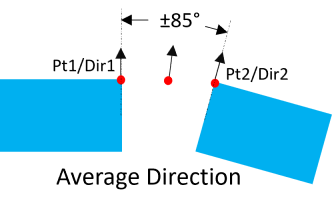
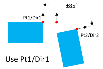
Directions - When creating between two parts: (73918) Depending on how the two points used to define a Dynamic Point, these rules were added to either use the Average Direction or to use the Pt1/Direction1.
•If the directions of the two points are within the scope of +85 degrees/-85 degrees, use the Average Direction.
•If the direction of the two points are outside the scope of +85 degrees/-85 degrees, use the Point1/Direction1 defined in the Dynamic Point dialog.
|
|
Note:•Using one point, the default vector of the Dynamic Point will be the same as the Control Point. The vector can be edited in the Points dialog. •The only Tolerance that can be applied to a Dynamic Points are Circle Tolerances and GD&T Size Tolerances.
|