|
|
Within this section:Adding Contents to a Spec Item
|
See Also...
|
For more information, below are DE Focus articles and a link to the Community forum to post questions.
Reference DE Focus Articles:Spec Study Seeing and Feeling Dimensional Objectives: (Issue 65) Spec Study by Influence Sphere Method: (Issues 67)
Leveraging High Definition Visualization in CATIA (Community)
|
|
Procedure:
To start a new Spec Study, the user will need to create a new Spec Items. Each Spec Item is created for one set of dimensional objectives and can contain multiple points and measurements.
1.Click on ![]() Spec Studies on the Model Creation toolbar and pick a component to create a new Spec Study.
Spec Studies on the Model Creation toolbar and pick a component to create a new Spec Study.
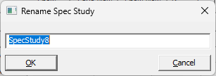
2.In the Spec Study dialog, click Add. This will add a new item in the list. Double-click on the new Spec Item to edit the name, or select Rename.
3.With the new Spec Item selected, add Measurements that have been created in the model.
4.Start editing the Spec Item:
a.Change the Type to change the Value, from Nominal to USL or LSL, or Specified if user defined value is required.
b.Add the parts to move when the measure is shown. Once the Comp1 or Comp2 is selected, only the part or sub-assembly the measured features resides in will be used.
To open a previously created Spec Study, double-click on a Spec Study in the Model Navigator.
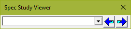
The Spec Study Viewer can be quickly show and apply each Spec Study. Open the Spec Study dialog and select Quick Viewer to load the Viewer toolbar.
The Spec Study Viewer toolbar isn't a free standing toolbar, and will need to be closed to return to the Spec Study dialog. |
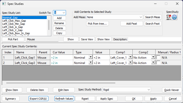
Spec Item List: Lists all available Spec Items. Users can add, delete, copy, rename or reorder the Spec Item.
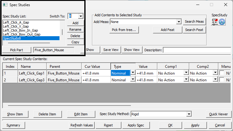
•Switch To: Use the Switch To list to move a Spec Study up or down in the list.
•Add: To create a new Spec Item, type in the name (ex. New_Spec_Item) in the Add box and press Enter. The newly created Spec Item will be added to the Spec Item List box, and will show up in the model assembly tree under SpecStudies list (after closing the dialog box).
•Rename: Allows the user to change the name of the selected spec item.
•Delete: Highlight the name of the spec item and click on the Del button. Click OK to delete the item and close the dialog box. Selecting Cancel will exit the dialog box without deleting the selected item.
•Copy: Will create a copy of the selected Spec Item, and move it to the end of the Spec Items list.
•Pick Part: Use this button to select a new component from the Navigation window where the Spec Studies will be created. The selected component will be shown in the window.
•Save View: Allows the user save the current camera view (what is currently shown in the graphics window) for the active Spec Study.
•Show View: will show the saved view for the active Spec Study.
•Description: A description of the Spec Study can be typed in this field. Although entering a description is optional, it helps users recall the Spec Study's function in their own words.
Adding Contents to a Spec Item:
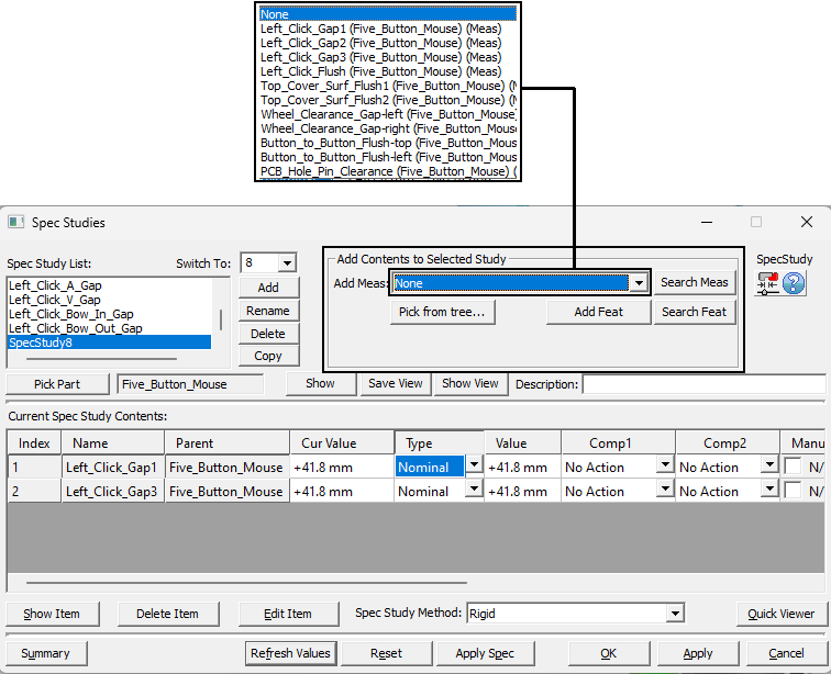
•Add Measure: Select the desired measure from the drop-down option to add it to the selected Spec Item list of measures. The newly added measure will show up in the Current Spec Item Contents area.
•Search Measure: Type in the desired measure name.
•Add Feat: Use this button to select the features from the Graph window.
•Search Feat: Type in the desired feature name.
•Spec Study Help button: The Help button is context sensitive; it will open the Help Manual at the Spec Study topic page.
Current Spec Item Contents (inputs)
•Name: Shows the measurement names listed for the selected Spec Item.
•Parent: Displays the parent part name for points and measures.
•Cur Value: Shows the current value of each measurement listed in the selected Spec Item. The color coding for the current measurement value results from comparing the Cur Value to the Value specified for the selected Type. If No Action is selected for both Spec Comp Lists, the two values are identical. The color coding is applied as follows:
oNo Action: black
oMatched value: green
oMismatched value: red
Type: Represents the setup for the selected measurement.
Type for Point to Point measurement can be: Nominal, Specified, LSL, or USL.
oNominal: Sets the desired distance between the measurement features to nominal distance.
oSpecified: Sets the desired distance between the measurement features to a user defined distance.
oLSL: Sets the desired distance between the measurement features to the lower spec limit.
oUSL: Sets the desired distance between the measurement features to the upper spec limit.
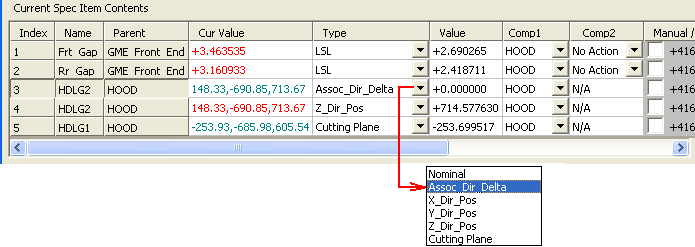
Type for individual points added to a Spec Item can be: Nominal, Assoc_Dir_Delta, X_Dir_Pos, Y_Dir_Pos, Z_Dir_Pos, Cutting Plane.
oAssoc_Dir_Delta: (This option is valid only for Influence Sphere method). Can be used to constrain or translate the part. To apply, select a Spec Item and add a point, using Add Feat button (see above). Enter a value in the Value column for the new point, and click Apply Spec (see below). The part in which the point was created will translate along the point's associated direction vector, by the amount specified in the Value column. To keep the part at nominal, leave the default (=0.00) number for the Value.
oX_Dir_Pos, Y_Dir_Pos, Z_Dir_Pos: Will constrain the selected item in the X, Y, or Z direction. The constrain position is displayed in the Value column. The item is allowed to slide along the other two (unconstrained) directions.
oCutting Plane: (This option is valid only for Influence Sphere method). Used to limit the deformation of the part to a certain area. To apply, select a Spec Item and add a point, using Add Feat button (see above), with the associated vector pointing towards the deformable area of the part. When the Spec Item is applied, the part deformation will occur only beyond the cutting point, along the point's direction vector. The point and it's associated vector are used to establish the Cutting Plane.
•Value: The measurement value for a specific Type.
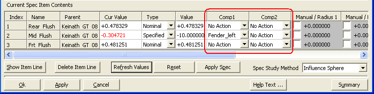
•Comp1: Represents the selected feature, or the first point of the selected measurement. If selected from the drop-down, the part will move when applying the Spec Item.
•Comp2: Represents the second point of the selected measurement. If selected from the drop-down, the part will move when applying the Spec Item.
Multiple parts can be moved for each scenario of the Spec Study. 3DCS has the ability to move parts as an assembly, assuming the 3DCS tree structure is organized in sub assemblies. |
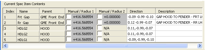
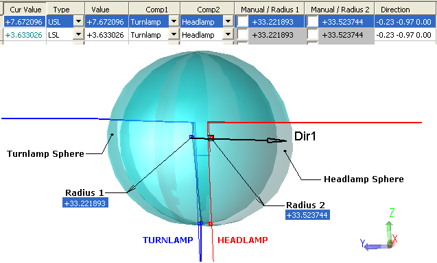
•Manual/Radius: This value represents the Influence Sphere radius, for each active measurement point in the spec study. This option allows the user to modify the radius calculated for each feature. Check the box to edit the radius value. Un-check the box to default back to the calculated value. To view the spheres for a gap or a flush, click the Show Item Line button:
•Direction: Shows the direction of each measurement.
•Description: This is the measurement description added in the measurement dialog box.
Spec Item Contents (Commands):

•Show Item Line: Will show the location and the direction of measurement, for the selected line, in the Graph window. Use the Close button to return to the previous dialog box.
•Delete Item Line: Will delete the selected line information.
•Go Item Line Dialog: Will open the measurement, or point dialog box for the selected item line.
•Quick Viewer: Will open a list to apply and scan through the available Spec Studies. The list will open based on what the user selected to edit. For example, if in a Spec Study Group of 12, only those 12 Spec Studies will be show in the list; or if at the top of the list, all Spec Studies will be shown in the list.
Spec Study Methods: There are three types of Spec Studies available:
•Rigid: Satisfies measurement values through rotations and translations of rigid objects.
•Influence Sphere: Satisfies measurement values through scaling geometry based on Influence Sphere methodology. The Influence Sphere Method deforms a component by following three steps:
oConstruct Influence Spheres
▪Find influence points from Input Constraints (measurement points).
▪Use the influence points as influence sphere centers.
▪Calculate the radii of influence spheres based on Input Constraints.
oDeform Influence Points
▪Deform the influence points as required in Input Constraints.
oPropagate the Influence Point deformation to the rest of components
▪Deform each non-influence-point in a component, according to the interrelationship with all influence spheres.
•Compliant: Satisfies measurement values through deforming geometry based on FE (Finite Element) methodology.
The 3DCS FEA Compliant Modeler license must be activated from within the 3DCS session and a session restart is required, when using this option. |
•OK: Will close the Setup Spec dialog and save the changes.
•Apply: Will apply all recent changes without exiting the dialog.
•Cancel: Will close the Setup Spec dialog and cancel all changes.
•Refresh Values: This function will update the Values of the Spec Studies, if when out of Nominal Build or another position, for example.
•Reset: Reset will reset the deformed CAD geometry in the graphics window.
•Apply Spec: This will apply the selected spec study and change the placement of the specified parts to the defined distance.
•Summary: Will open a dcs_rel_item_sum.tmp file (using Notepad), and list all parameters for the Spec Items included in the Spec Item List. Select File/Save As to save the data in text format.
Export CGRs: Users can save specific Spec Limit positions, as well as deformed geometry, a save them as CGR or CAD Geometry. In the Spec Study dialog, select Export CGR(s). This will make a new CATIA CGR file, based on the position and deformation of the CAD geometry.
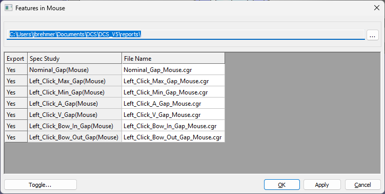
1.Select the [Export CGRs] button.
2.In the Export CGRs menu, select the Spec Studies to export as a CGR file.
3.Select [Toggle] or Double-Click on the line to switch from Yes to No.
4.Select OK to export the CGR files.
5.Optional: change the location where the CGRs are created. The default location: C:\Users\<username>\Documents\DCS\DCS_V5\reports\
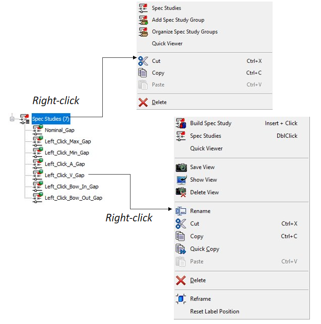
 Spec Study Navigations
The Spec Studies can be easily activated by double clicking in the Model Navigator: •Single-click on a Spec Studies in the Model Navigator, will build the Spec Study to it's available and current content. •Double-clicking on Spec Studies in the Model Navigator, will open the spec study dialog box. •Clicking on a Spec Item in the Spec Study dialog, will allow the user to edit that Spec Study dialog for that Spec Item.
|
Error Messages
There are some cases when the Influence Sphere cannot propagate the Influence Points deformation to the rest of components.
When the angle between the Influence Points' vectors is larger then 95 degrees, an error message will tell the user that the surface cannot be deformed using the Influence Sphere method:
To solve this issue, additional Influence Sphere (measurement) should be created between the two initial ones. This will reduce the angle between every two consecutive measurements' vectors, to a value less than 45 degrees.
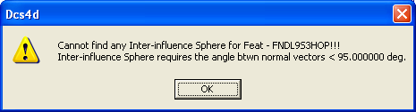
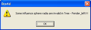
When only one measurement is activated in the Spec Study:
The following warning will appear on the screen:
To solve this issue, one more component in the Spec Comp List should be selected.
|
Notes:For Spec Studies to function consistently: The measurements used in a spec study must be active and Nominal Build is required. Due to the Nominal Build process, the Spec Studies will use the measurements to pull the nominal value, measurement vector direction, USL and LSL. Once this information is obtained, the measurement vector direction used in the Spec Studies is a fixed direction. (i.e. Type-In vector direction). If the actual vector direction used in the measurement is set to Associated, users will receive a Validation warning from the Spec Studies using that measurement. When a Spec Study is implemented, the final results of the Spec Study may not match the actual measurement value because the Associated vector in the measurement may have changed (rotating the Parts). "Measure | 'Model Name' | 'Item Name' | "Has an associated direction used in 'Spec Study'"
This is only a warning and can be settled by changing the vector direction in your measurement to Type-In instead of Associated.
|