In CATIA V5, the FT&A workbench allows users to define tolerances, such as Size tolerances for a feature of size, either diametrical or linear size.
How to create:Diametrical Size Tolerance Linear Size Tolerance Best Practices
|
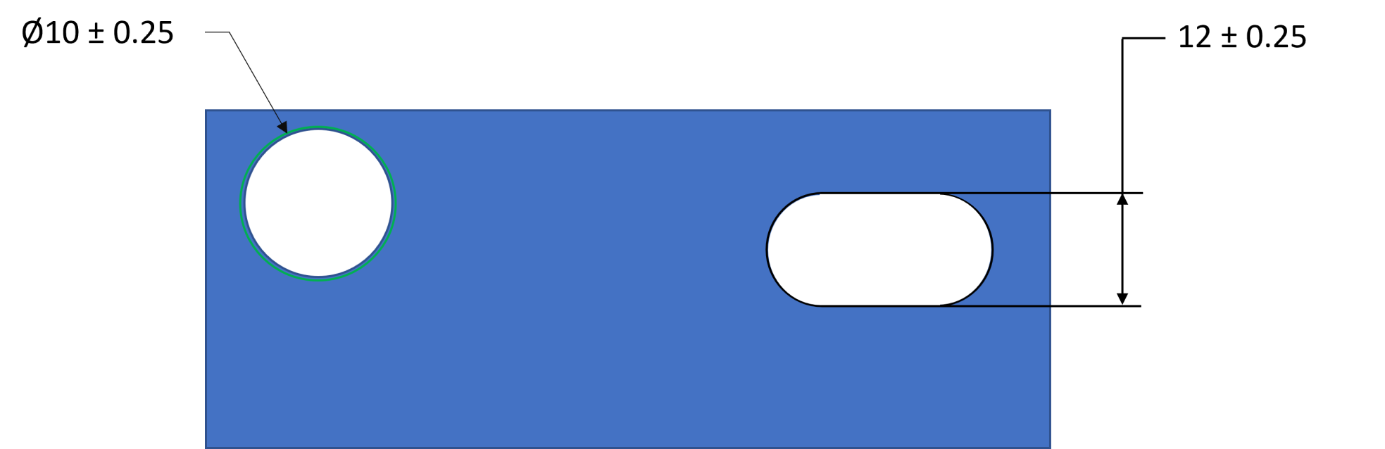
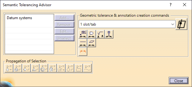
Creating a diametrical Size Tolerance: 1.Open the 2.Select a hole or pin, 3.Click the diameter button in the Tolerance Advisor |
(CATIA V5-6R2022) |
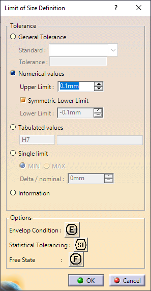
General Tolerance: Will add a standard tolerance depending on the Standard the GD&T is created in. Four standards are automatically created but is not modifiable. oANSI B4.3-1978-f (+0.15, -0.15) oANSI B4.3-1978-m (+0.3, -0.3) oANSI B4.3-1978-c (+0.8, -0.8) oANSI B4.3-1978 (+0.8, -0.8) Numerical Values: Will add the numerical tolerance (ex: +/-0.1) to the 3DEXPERIENCE GD&T call-out and is used in 3DCS. Turning off Symmetric Lower Limit: will show a upper and lower tolerance value, each value can be edited. (ex: +0.5, -0) Tabulated Values: Is a standard created size tolerance. The tolerances available are not modifiable; however, a user can use a letter/number sequence ranging from A to G and 1 to 9. The setting can be used in 3DCS. Single Limit: Will show a MIN or Max value on the 3DEXPERIENCE call-out (ex: 5.5 MAX). By adding a Delta/Nominal value, the range and offset will be modified in 3DCS to apply the MIN or MAX variation value. Information: Will display the value as a Basic Dimension (5.45). (Basic Dimensions will not be creating in 3DCS, when Extracting GD&T). |
(CATIA V5-6R2022) |
Note: Extracting a Linear Size tolerance from 3DEXPERIENCE will automatically create a
|
Best Practices - Using FT&A to create measures (in 3DCS):
CATIA V5 users can also create a Linear Size tolerance, between two parts, when creating GD&T in an assembly. This will produce a dimension between two parts, within a range defined by the tolerance. Instead of extracting the GD&T as a tolerance, use ![]() Extract Measures, under the same menu as Extract GD&T, to create a Dimensioning Distance Measure. The tolerance range will be set as the USL/LSL in the measure.
Extract Measures, under the same menu as Extract GD&T, to create a Dimensioning Distance Measure. The tolerance range will be set as the USL/LSL in the measure.
Requirements:
Semantic Linear Tolerance
Dimensions created in the Assembly/sub-assembly level