|
![]() Creating Coordinate Point on Solid
Creating Coordinate Point on Solid
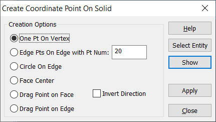
•Click on Geometry tab and select •This brings up the Create Coordinate Point On Solid dialog box.
•Select the Creation option desired. •Click Select Entity and select a Point, Edge or Face. •Select Show to display the edge selected and vector direction. •Select Apply when finished. Commands •Invert Direction will invert the direction of the vector associated with the selected point. •Help: Opens the Help Manual at the Create Coordinate Point on Solid page. •Select Entity: This selects the entity to modify or create. This function is required to modify or create all options in the Create Coordinate Point on Solid dialog. Note: Shaded with Edges graphics display is required. •Show: Shows the new location or new created points before selecting Apply. •Apply: Applies the changes or creates the points. •Select Close to exit. |
|---|
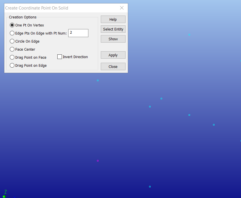
One Pt On Vertex will create a point from the selected vertex. Before using this function, go to the Display tab and switch the Shading to Points Only. 1.Select the One Pt on Vertex option. 2.Click [Select Entity]. 3.Select one of the vertex points shown in the view and select [Apply].
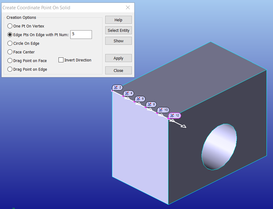
Edge Pts On Edge with Pt Num will generate the specified number of segments along the selected edge. The points will follow the edge direction. Users can use the Edge Direction function or Edit Point dialog to change Edge or Point direction. 1.Select the Edge Pts On Edge with Pt Num option. 2.specify an amount of points to create. 3.Click [Select Entity] and select an edge. 4.Select [Apply].
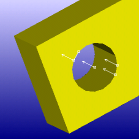
Circle On Edge will create a center of an edge and define a Circle Size tolerance. 1.Select the Circle on Edge option. 2.Click [Select Entity] and select an circle edge. (Fillet edge, hole edge, etc.) 3.Select [Apply].
Face Center will generate a point in the center of a surface. 1.Select the Face Center option. 2.Click [Select Entity] and select a surface. 3.Select [Apply].
Drag Point on Face will allow the user to move a point on the selected face. 1.Select the Drag Point on Face option. 2.Click [Select Entity] and select an existing Coordinate Point and hold the left-mouse button. The mouse icon will change to '+', move the point while in this mode. 3.Close the selection dialog. 4.Select [Apply]. Drag Point on Edge will generate a point at the selected edge. 5.Select the Drag Point on Edge option. 6.Click [Select Entity] and select an existing Coordinate Point and hold the left-mouse button. The mouse icon will change to '+', move the point while in this mode. 7.Close the selection dialog. 8.Select [Apply]. |
|---|
