A ![]() Straightness GD&T is typically used to vary the form of an axial feature (such as a pin or hole). It can also be used to vary the form of a planar surface. Similar to as it may be found on a drawing,
Straightness GD&T is typically used to vary the form of an axial feature (such as a pin or hole). It can also be used to vary the form of a planar surface. Similar to as it may be found on a drawing, ![]() Straightness can be applied as a prequalifier on a Datum or as a refinement of another GD&T callout. A
Straightness can be applied as a prequalifier on a Datum or as a refinement of another GD&T callout. A ![]() Straightness GD&T has two separate behaviors depending on the zone shape that is selected. Both will be explained in this section.
Straightness GD&T has two separate behaviors depending on the zone shape that is selected. Both will be explained in this section.
Creating Straightness Procedure:
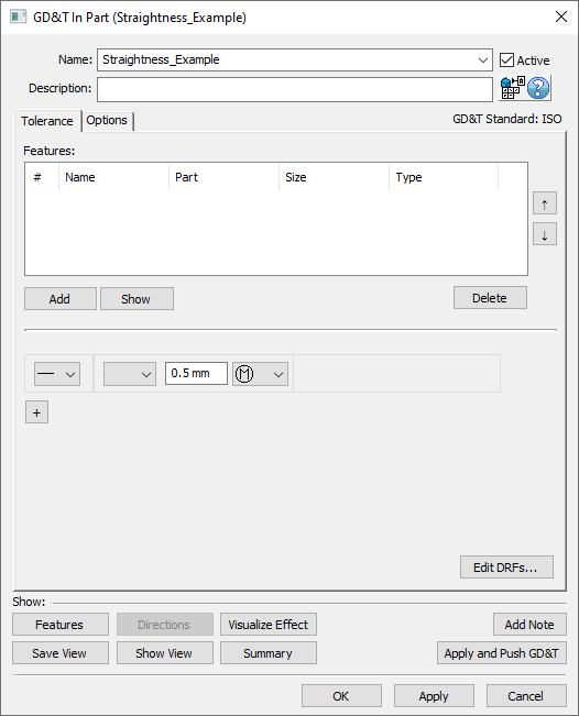
1.In the GD&Ts dialog, select ![]() Straightness in the drop-down list and select [Add GD&T]. This will open up the GD&T dialog.
Straightness in the drop-down list and select [Add GD&T]. This will open up the GD&T dialog.
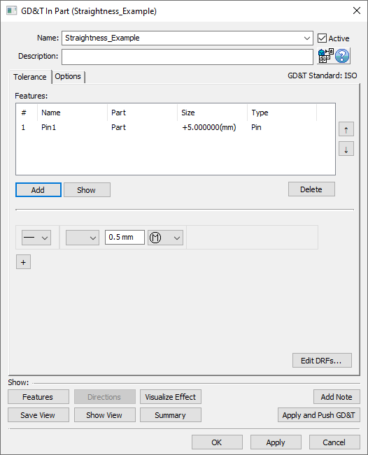
2.Underneath the Features list, select [Add].
3.Select the feature(s) whose form should be varied by this GD&T.
4.Click [OK][Close] in the Pick FeatureSelect dialog
At this point the GD&T dialog will pop back up. Notice that the features selected are now in the Features list in the top half of the dialog.
5.Select the zone type from the zone type drop down (linear zone or diametrical zone).
6.Enter the range in the text entry field.
7.If applied to a Feature of Size, select the material modifier from the Material Modifier drop-down (blank for RFS, ![]() for MMC, or
for MMC, or ![]() for LMC).
for LMC).
8.Select [OK] to exit the dialog and the save the GD&T.
How this GD&T Varies the Feature - Diametrical Zone:
A ![]() Straightness GD&T applied with a diametrical zone to a pin or hole, will vary the form of the axis of the feature. This means that the size at each cross-section of the pin or hole will not change, but the location of the center point of the cross-section will. The location of the center point of each cross-section will deviate independently of the other cross-sections (this differs from a
Straightness GD&T applied with a diametrical zone to a pin or hole, will vary the form of the axis of the feature. This means that the size at each cross-section of the pin or hole will not change, but the location of the center point of the cross-section will. The location of the center point of each cross-section will deviate independently of the other cross-sections (this differs from a ![]() Position GD&T where all of the center points of a feature will deviate together.
Position GD&T where all of the center points of a feature will deviate together.
A sample pin feature with how a ![]() Straightness GD&T and diametrical zone would commonly deviate it is shown below.
Straightness GD&T and diametrical zone would commonly deviate it is shown below.
Note: While only a few deviated locations are shown below, the actual variations will use the entire specified zone.
A side view of a pin with a Straightness GD&T and diametrical zone applied to it.
![]() Straightness with a diametrical zone can only be applied to axial features.
Straightness with a diametrical zone can only be applied to axial features.
How this GD&T Varies the Feature - Linear Zone:
A ![]() Straightness GD&T can also be applied to the surface of a feature using the linear zone option. When applied to a planar/flat surface, each node on the feature will deviate independently of all other nodes. When applied to the surface of a hole or pin (i.e. there is a
Straightness GD&T can also be applied to the surface of a feature using the linear zone option. When applied to a planar/flat surface, each node on the feature will deviate independently of all other nodes. When applied to the surface of a hole or pin (i.e. there is a ![]() Straightness GD&T applied to a hole or pin feature without the diametrical zone symbol in the feature control frame), then the size of each cross section of the hole or pin will deviate independently of the other cross-sections while the center points of the cross-sections will remain co-linear. This differs from a
Straightness GD&T applied to a hole or pin feature without the diametrical zone symbol in the feature control frame), then the size of each cross section of the hole or pin will deviate independently of the other cross-sections while the center points of the cross-sections will remain co-linear. This differs from a ![]() Size GD&T where the sizes of each cross-section all change together as a group.
Size GD&T where the sizes of each cross-section all change together as a group.
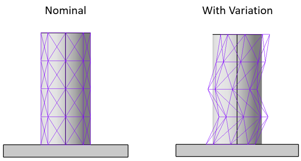
A ![]() Straightness GD&T applied to a planar surface and a pin feature are shown below. When deviating form, each node or diametrical size on the feature will deviate independently of all other nodes or diametrical feature on the surface.
Straightness GD&T applied to a planar surface and a pin feature are shown below. When deviating form, each node or diametrical size on the feature will deviate independently of all other nodes or diametrical feature on the surface.
Note: While only a few deviated locations are shown below, the actual variations will use the entire specified zone.
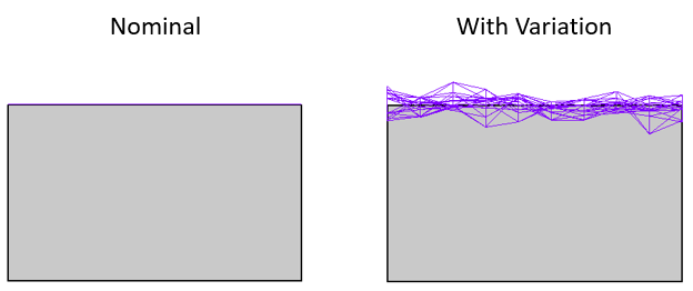
A side view of a face with a Straightness GD&T and linear zone applied to it.
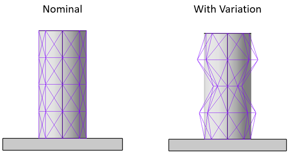
A side view of a pin with a Straightness GD&T and linear zone applied to it.
In accordance with ASME and ISO rules, ![]() Straightness with a linear zone can only be applied to a feature that is nominally straight. To apply a form tolerance to a curved surface, see Surface Profile.
Straightness with a linear zone can only be applied to a feature that is nominally straight. To apply a form tolerance to a curved surface, see Surface Profile.
Note: ![]() Straightness with a linear zone on a planar surface has the same deviation routine as
Straightness with a linear zone on a planar surface has the same deviation routine as ![]() Flatness.
Flatness.
Note: ![]() Straightness with a linear zone on an axial feature has the same deviation routine as
Straightness with a linear zone on an axial feature has the same deviation routine as ![]() Circularity or
Circularity or ![]() Cylindricity.
Cylindricity.
Applying Maximum Material Condition (MMC) or Least Material Condition (LMC) for Bonus:
Material Modifiers are allowed for a ![]() Straightness GD&T for a feature that also has a
Straightness GD&T for a feature that also has a ![]() Size GD&T. 3DCS will give an error if
Size GD&T. 3DCS will give an error if ![]() for MMC, or
for MMC, or ![]() for LMC are present in the Material Modifiers drop-down for a feature that does not also have size variation. For more information on Bonus Tolerance see Bonus Tolerance.
for LMC are present in the Material Modifiers drop-down for a feature that does not also have size variation. For more information on Bonus Tolerance see Bonus Tolerance.
Rate of Change/Unit Basis:
For a ![]() Straightness GD&T it is possible to use the Unit Basis section of the Options tab. See Unit Basis for more information.
Straightness GD&T it is possible to use the Unit Basis section of the Options tab. See Unit Basis for more information.
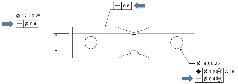
Straightness as a Refinement:
It is common for ![]() Straightness to be a refinement of a location GD&T such as
Straightness to be a refinement of a location GD&T such as ![]() Position such as what is seen in the image below. If this is the case then 3DCS by default uses an RSS methodology to take the refinement into account without exceeding the limits of the location boundary. Settings for this can be changed depending on GD&T deviation method or Distribution input. See RSS Method for more information. An example callout for this is shown below.
Position such as what is seen in the image below. If this is the case then 3DCS by default uses an RSS methodology to take the refinement into account without exceeding the limits of the location boundary. Settings for this can be changed depending on GD&T deviation method or Distribution input. See RSS Method for more information. An example callout for this is shown below.
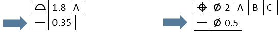
An example of a callout where Straightness is a refinement of the Position GD&T.