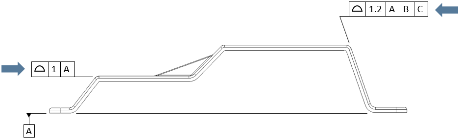
A ![]() Surface Profile GD&T is typically used to vary the location of a planar or curved surface. It can also be used to vary the form of a surface or the size of a Feature of Size. Note that even though in ASME or ISO a Surface Profile GD&T is controlling location, orientation, and form, in 3DCS it is only controlling location. For this reason, it may be necessary to add refinements to the GD&T that are not on the drawing.
Surface Profile GD&T is typically used to vary the location of a planar or curved surface. It can also be used to vary the form of a surface or the size of a Feature of Size. Note that even though in ASME or ISO a Surface Profile GD&T is controlling location, orientation, and form, in 3DCS it is only controlling location. For this reason, it may be necessary to add refinements to the GD&T that are not on the drawing.
Creating Surface Profile Procedure:
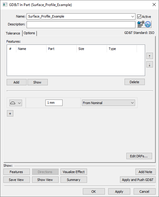
1.In the GD&Ts dialog, select ![]() Surface Profile in the drop-down list and select [Add GD&T]. This will open up the GD&T dialog.
Surface Profile in the drop-down list and select [Add GD&T]. This will open up the GD&T dialog.
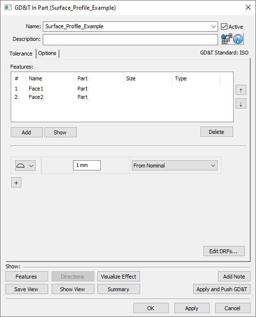
2.Underneath the Features list, select [Add].
3.Select the feature(s) whose location (or form) should be varied by this GD&T.
4.Click [OK][Close] in the Pick FeatureSelect dialog
At this point the GD&T dialog will pop back up. Notice that the features selected are now in the Features list in the top half of the dialog.
5.Enter the range in the text entry field.
6.Select No DRF, a DRF, or From Nominal from the Datum Reference Frame drop-down. See Datum Reference Frames for more information about creating and using DRFs.
7.Select [OK] to exit the dialog and the save the GD&T.
How this GD&T Varies the Feature - DRF or From Nominal:
A ![]() Surface Profile GD&T with a DRF or From Nominal selected is the most common use of the
Surface Profile GD&T with a DRF or From Nominal selected is the most common use of the ![]() Surface Profile GD&T. The
Surface Profile GD&T. The ![]() Surface Profile GD&T only varies the location of the feature which means that the orientation and form of the feature remain perfect. The location of the feature is varied within the specified zone. The direction of the zone is determined by the direction of the surface selected. If the surface is not planar then each mesh node on the surface will vary along the direction normal to itself. An example of this is displayed in the second image below. If a
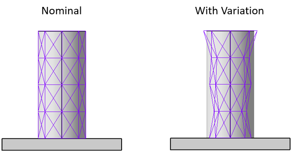
Surface Profile GD&T only varies the location of the feature which means that the orientation and form of the feature remain perfect. The location of the feature is varied within the specified zone. The direction of the zone is determined by the direction of the surface selected. If the surface is not planar then each mesh node on the surface will vary along the direction normal to itself. An example of this is displayed in the second image below. If a ![]() Surface Profile GD&T is applied to a Feature of Size such as a pin or hole then the diametrical size of the feature will vary while the axis remains unchanged relative to the DRF. This is shown in the third image below.
Surface Profile GD&T is applied to a Feature of Size such as a pin or hole then the diametrical size of the feature will vary while the axis remains unchanged relative to the DRF. This is shown in the third image below.
A few sample features with how a ![]() Surface Profile GD&T would commonly deviate them are shown below.
Surface Profile GD&T would commonly deviate them are shown below.
Note: While only a few deviated locations are shown below, the actual variations will use the entire specified zone.
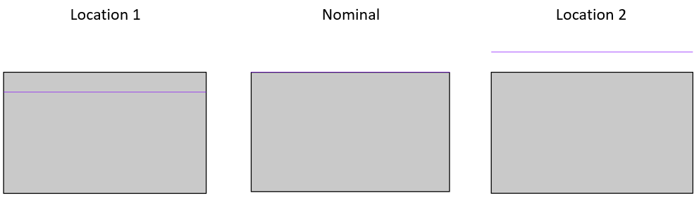
A side view of a face with a Surface Profile GD&T applied to it set to either a DRF or From Nominal.
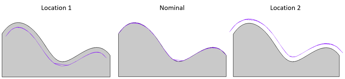
A side view of a curved surface with a Surface Profile GD&T applied to it set to either a DRF or From Nominal.
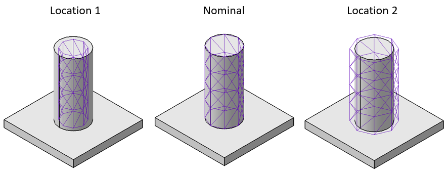
A pin with a Surface Profile GD&T applied to it set to either a DRF or From Nominal.
Any feature will work with a ![]() Surface Profile GD&T.
Surface Profile GD&T.
Note:
•Points defined with a Circle Size will deviate as location, when applying a Surface Profile on the circle point in the point's vector direction.
•If no Size is applied to the point, Surface Profile will also deviate the Point as Location, along the point's vector direction. (73019)
•While size is varied for a pin or hole feature using the ![]() Surface Profile GD&T, this will not be taken into account for Bonus Tolerance or Datum Shift in any other GD&T. See Bonus Tolerance and Datum Shift for more information.
Surface Profile GD&T, this will not be taken into account for Bonus Tolerance or Datum Shift in any other GD&T. See Bonus Tolerance and Datum Shift for more information.
How this GD&T Varies the Feature - No DRF:
A ![]() Surface Profile GD&T set to No DRF will control the form of the feature(s) in the Features list. As
Surface Profile GD&T set to No DRF will control the form of the feature(s) in the Features list. As ![]() Flatness or
Flatness or ![]() Straightness cannot be applied to a curved surface, this is the only option for applying form variation to any curved surfaces. When deviating form, each node on the feature will deviate independently of all other nodes on the surface. This differs from the location tolerance because the location tolerance is deviating all of the nodes together. When applied to a a feature of size such as a pin or hole, the size will vary independently at each cross section of the feature, but the axis will still remain perfect. This deviation style is identical to how 3DCS treats
Straightness cannot be applied to a curved surface, this is the only option for applying form variation to any curved surfaces. When deviating form, each node on the feature will deviate independently of all other nodes on the surface. This differs from the location tolerance because the location tolerance is deviating all of the nodes together. When applied to a a feature of size such as a pin or hole, the size will vary independently at each cross section of the feature, but the axis will still remain perfect. This deviation style is identical to how 3DCS treats ![]() Circularity,
Circularity, ![]() Cylindricity, or
Cylindricity, or ![]() Straightness (linear zone on a pin or hole). An example of this is shown in the third image below.
Straightness (linear zone on a pin or hole). An example of this is shown in the third image below.
Sample features with how a ![]() Surface Profile GD&T set to No DRF would commonly deviate are shown below.
Surface Profile GD&T set to No DRF would commonly deviate are shown below.
Note: While only a few deviated locations are shown below, the actual variations will use the entire specified zone.
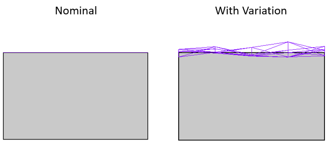
A side view of a face with a Surface Profile GD&T applied to it set to No DRF.
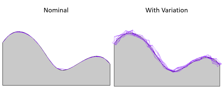
A side view of a curved surface with a Surface Profile GD&T applied to it set to No DRF.
A pin with a Surface Profile GD&T applied to it set to No DRF.
Composite Surface Profile GD&T:
Composite GD&T for a ![]() Surface Profile GD&T can be created within 3DCS. See Composite GD&T for more information.
Surface Profile GD&T can be created within 3DCS. See Composite GD&T for more information.
Rate of Change/Unit Basis:
For a ![]() Surface Profile GD&T set to No DRF it is possible to use the Unit Basis section of the Options tab. See Unit Basis for more information.
Surface Profile GD&T set to No DRF it is possible to use the Unit Basis section of the Options tab. See Unit Basis for more information.
Best Practices:
When to apply Group All Features for Common Zone modifier; and for Location, Orientation and Form: When to apply Group All Features in 3DCS, when the Common Zone (CZ) modifier is required. If the user needs to apply a refinement, For Profile tolerance, and when to apply refinements to the same feature.
•If the user wants CZ for Location - Do nothing. By varying relative to the same DRF or From Nominal, the Features in the list will inherently vary within the same zone!
•If the user wants CZ for Orientation (and presumably Location) then add Group All Features to the Location call-out and leave it turned off for the Orientation. This will vary the Orientation Zones together relative to the DRF but the individual Features will be allowed to vary independently of each other within that Orientation Zone.
•If the user wants CZ for Form (and presumably Location & Orientation) then Group All Features would need to be toggled On for Location & Orientation and turned off for Form.
Applying Surface Profile to a Point: Users will be able to apply Surface Profile to a point, instead of needing to make a separate point to Simulation location of a surface.
Example: Position on Features of Size with a Surface Profile on a surface.
1.Extract the GD&T to create the Position and Size tolerances.
2.Create the Points to simulation the Surface Profile. They can be Feature Points, set to Center of the Feature or Coordinate Points with a Circle Size.
3.Create a new Surface Profile. Edit the Range and set a DRF (the options can only be From Nominal or to a set of Datums).
4.Select the Points in the Feature field.
5.In the Options tab, turn On the Custom Direction option. Turning Off the Auto Refinement option will prevent any validation messages, since points are being used in the Surface Profile GD&T.
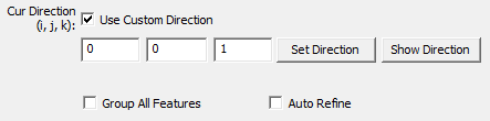
6.Set the direction using the ijk field. More options are available in the Set Direction option.