Procedure:
1.Open a model
2.Switch to the Assembly Design workbench.
3.Locate the Constraints toolbar.
4.Start by creating a Fix Constraint on a Part. Select the Fix icon and select a part to Fix in space.
Assembly Constraints (Assembly Design)
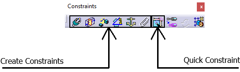
The Constraints toolbar is available in the Assembly Design. Users can apply a Coincidence, Surface Contact, Offset, Angle, Fix and Fix Together.
•![]() Coincidence Constraint - Coincidence-type constraints are used to align elements, i.e.: surface to surface or axis to axis.
Coincidence Constraint - Coincidence-type constraints are used to align elements, i.e.: surface to surface or axis to axis.
•![]() Contact Constraint - Contact-type constraints can be created between two directed surfaces. Directed means that an internal side and an external side can be defined from a geometrical element, a face of a pad for example.
Contact Constraint - Contact-type constraints can be created between two directed surfaces. Directed means that an internal side and an external side can be defined from a geometrical element, a face of a pad for example.
•![]() Offset Constraint - This function consists of applying an offset constraint between two faces.
Offset Constraint - This function consists of applying an offset constraint between two faces.
•![]() Angle Constraint - This function consists of setting an angle constraint between two planes.
Angle Constraint - This function consists of setting an angle constraint between two planes.
•![]() Fix Constraint - Fixing a component means preventing this component from moving from its parents during the update operation.
Fix Constraint - Fixing a component means preventing this component from moving from its parents during the update operation.
•![]() Fix Together Constraint - This function consists of fixing two or more components together.
Fix Together Constraint - This function consists of fixing two or more components together.
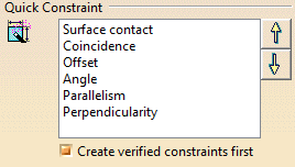
Quick Constraint - applies a constraint between two elements, based on the set priority list. Go to Tools -> Options, select Mechanical Design, select Assembly Design and then select the Constraints tab.
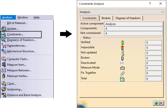
Analyzing Constraints - Shows the different issues involving Constraints in the active assembly. In Assembly Design, select the Analyze menu and select Constraints...
|
In the Constraints tab: •Shows if the available constraints are Broken, Deactivated; •Shows the total amount of constraints in the active assembly.
The Broken tab shows the list of broken Constraints in the active assembly. For example, the list may show: (The bracket "(5)" values shows the order; the value "*.5" in the constraint is apart of the name). •Fix.5 (1) •Coincidence.4 (2) •Surface Contact.3 (3)
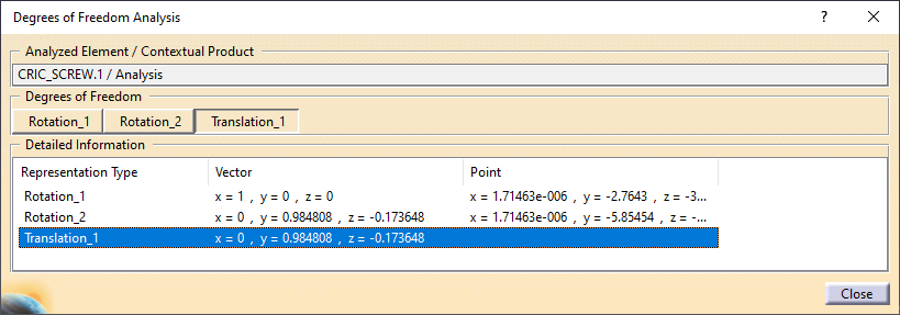
Degrees of Freedom tab shows the amount of Degrees of Freedom applied, based on the Assembly Constraints. Double-clicking on any of the items in the list will show the applied Degrees of Freedom: Translations and Rotation, by the vector direction and the point location.
|
3DCS Constraint Extraction
CATIA V5 Constraints |
3DCS Constraints |
|
|
|
|
|
|
|
|
|
|
|