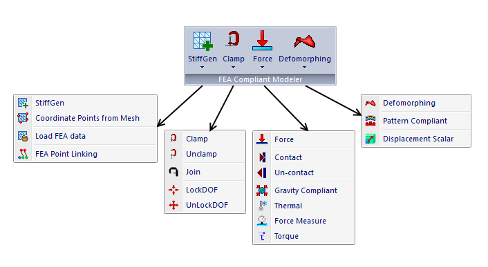
3DCS FEA Compliant Modeler is an add-on module to 3DCS Variation Analyst, which enhances the existing 3DCS capability (Bend Move, Auto-Bend) to model compliant parts and assemblies.
To learn more: •3DCS FEA Compliant Modeler Tutorials •Compliant Modeler (Community Forums)
|
This module utilizes Finite Element Mesh and Stiffness Matrix data generated externally so that 3DCS can more accurately simulate variation of compliant parts and assemblies than the existing capability in 3DCS.
3DCS FEA Compliant Modeler simulates compliant part deformation resulting from manufacturing operations such as clamping, welding, unclamping, and force application. 3DCS FEA Compliant Modeler deforms the parts during simulation based on the part stiffness matrix for each compliant part identified within the 3DCS model.
The 3DCS FEA Compliant Modeler is seamlessly integrated with the existing capabilities of 3DCS, that is, the compliant routines will be used with the existing 3DCS model creating capability including the Measurements, Rigid Body Moves and Tolerances.
The FEA Compliant Modeler Toolbar will be displayed when the license is selected.

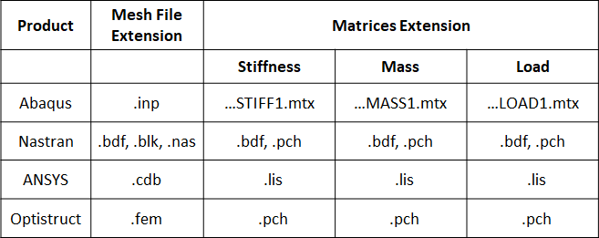
Supported Meshes and Solvers

oThe MSC Nastran *.dat input deck is supported, but the file should be renamed as *.nas before attempting to load it into the Load FEA Data move.
oThe *.dat file extension was not added to the list of input deck files, to avoid confusion with the Abaqus output file used in the Displacement Scalar.
Meshing multiple instances in Catia V5
Creating a copy of a part then meshing it can sometimes result in large distances between the points on the part and selected mesh nodes, due to the different coordinate system for the new part. In this case the part and the mesh created are not at the same location. To avoid this situation, use the following steps to create the new part:
1. Copy the part
2. Go to Start ->Shape ->Generative Shape Design
3. Use the Translate from the Operations toolbar to reposition the part. This way you preserve the same global coordinates for the original and for the copied part.
Rigid Body Elements (RBE2 and RBE3) - available for some meshers.
Only RBE2 elements are supported with 3DCS Compliant Modeler module when using the Join move to connect the "independent nodes".
Explanation of the elements different behavior:
Both elements "look" the same, in that they have a single node connected to one or (usually) multiple other nodes. The difference is that the RBE2 element adds (infinite) stiffness to the structure, while RBE3 elements "distribute forces" around the connected nodes, without adding any stiffness.
•For an RBE2 rigid element, the single node is the "independent node". It has 6 degrees of freedom, regardless of what your FEA graphical interface looks like. The other node(s) you select are the dependent nodes. You decide which of their degrees of freedom you wish to connect.
•The RBE3 “rigid” element is not actually “rigid”, however, it also is used to “connect” the DOF's at one or (typically) multiple independent nodes to a single dependent node. The motion of the single dependent node is a “factored interpolation” of the motion at the independent nodes – based on the DOF you choose to connect and the interpolation factor(s) you choose for the independent nodes. In practice, the RBE3 is often used to distribute the effect of a force or mass or constraint acting at the dependent node over a number of other nodes (the independent nodes), without adding stiffness to the structure.
Keywords
•The Reduced Stiffness Matrix analysis set is identified by a set of keywords, specific to the type of solver used:
•For files generated using Abaqus solver the keyword used is: nset-DCSSET or DCSASETSET.
•For files generated using Nastran solver the keyword used is: ASET 6836123, where ASET means analysis set, 6836 is the grid point identification number (specific for each grid point), and 123 represents the component number of global coordinates restricted (up to six unique digits may be placed in the field with no embedded blanks).
To increase accuracy the users should create a finer mesh with higher-order elements (such as quadratic rather than linear).
➢ A linear element, or a lower order element is characterized by a linear shape function. The displacements of the mesh region between the nodes varies linearly with the distance between the nodes. Linear elements do not capture bending.
➢ A quadratic element, or a higher order element utilizes a non-linear shape function. The displacements between the nodes are interpolated using a higher order polynomial. These elements have mid-side nodes – An element edge would consist of three nodes instead of two. Quadratic elements are better suited to represent complex geometries and bending deformations. Quadratic elements are computationally more expensive than linear elements.

Lower order tetrahedral elements will make the model overly stiff and should be generally avoided.
Notes: For step-by-step instructions, examples and other helpful information on how to generate the FEA files, follow these links to the Community:
oHow to generate Mesh and Stiffness Matrix using ABAQUS
oHow to generate Mesh and Stiffness Matrix using Hypermesh
oHow to generate Mesh and Stiffness Matrix using Ansys - we are using substructuring analysis to get stiffness matrix. Please refer to the Ansys documentation to see which element types support substructuring.
oHow to create Rigid Connection Elements (RBE2) in ABAQUS
oHow to create Rigid Body Elements (RBE2) in Hypermesh
oHow to use NXNastran to generate stiffness matrices
oHow to use NEiNastran to generate stiffness matrices
Superelement
The reduced stiffness matrix is created using a superelement. A superelement simply represents a collection of elements that are reduced to act as one element. The principle used in superelement analysis is often referred to as substructuring. That is, the model is represented by a single component (superelement), processed independently to create a reduced matrix that describes the behavior of the superelement. In static analysis the theory used in superelement processing is exact (not an approximation).
To define an external superelement, the user simply identifies the interface DOF on ASET cards. Every DOF that is not identified on an ASET is treated as an interior DOF, while the DOFs identified on ASETs are considered external DOFs and included in the stiffness matrix.
ASET Points
•The user needs to have mesh nodes identified for all modeling points used in compliant moves and in measurements. StiffGen will automatically select nodes for all modeling points in the part.
•If the user wants to visually observe the deformation of the part (during Animation), the user should create extra points that would cover the part's surface (like a mesh with a very big step).
The part's deformation is not necessary; model's results will be reported by measurements, not visually, and the measurements will be accurate since the points measured will be toleranced and also linked to mesh nodes.
The number of points created on the part should be kept at minimum, especially in larger models. Too many points will slow down the model calculation time. For every compliant move in every Monte Carlo simulation, we will calculate this equation based on the boundary conditions:
[K]{d}= {F}
where,
[K] is the 3n x 3n stiffness matrix (or 6n x 6n depending on the DOF of the nodes),
{d} is the displacement vector, {F} is the force vector.
This is the most time-consuming calculation in the compliant model, so we want to keep the stiffness matrix [K] as small as possible. To do that, please delete the unnecessary modeling points in the model. All coordinate and feature points in a compliant part will have a corresponding mesh node that will be included in the stiffness matrix.
•The compliant moves and measurements should be created prior to input deck and reduced stiffness matrix, so that all points are included in the nodes set.
•StiffGen automatically links the 3DCS modeling points to (external) mesh closest nodes. Then the solver is called and the reduced stiffness matrix is generated. The new created input deck and stiffness matrix will be loaded in the Load FEA Data move. This operation can be repeated as many time is necessary.