A ![]() Perpendicularity GD&T is used to vary the orientation of a planar or axial feature (such as a hole or pin). Note that even though in ASME or ISO a Perpendicularity GD&T is implicitly also controlling form, in 3DCS it is only controlling orientation (form remains perfect). For this reason, it may be necessary to add refinements to the GD&T that are not on the drawing.
Perpendicularity GD&T is used to vary the orientation of a planar or axial feature (such as a hole or pin). Note that even though in ASME or ISO a Perpendicularity GD&T is implicitly also controlling form, in 3DCS it is only controlling orientation (form remains perfect). For this reason, it may be necessary to add refinements to the GD&T that are not on the drawing.
Creating Perpendicularity Procedure:
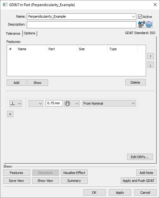
1.In the GD&Ts dialog, select ![]() Perpendicularity in the drop-down list and select [Add GD&T]. This will open up the GD&T dialog.
Perpendicularity in the drop-down list and select [Add GD&T]. This will open up the GD&T dialog.
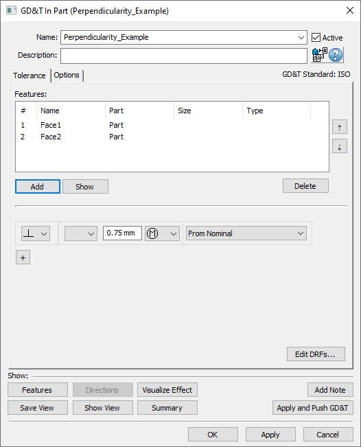
2.Underneath the Features list, select [Add].
3.Select the feature(s) whose orientation should be varied by this GD&T.
4.Click [OK][Close] in the Pick FeatureSelect dialog
At this point the GD&T dialog will pop back up. Notice that the features selected are now in the Features list in the top half of the dialog.
5.Select the zone type from the zone type drop down (linear zone, or diametrical zone).
6.Enter the range in the text entry field.
7.Select the material modifier from the Material Modifier drop-down (blank for RFS, ![]() for MMC, or
for MMC, or ![]() for LMC).
for LMC).
8.Select a DRF or From Nominal from the Datum Reference Frame drop-down. See Datum Reference Frames for more information about creating and using DRFs.
9.Select [OK] to exit the dialog and the save the GD&T.
How this GD&T Varies the Feature - Linear Zone:
When applying a ![]() Perpendicularity GD&T to a planar surface, a linear zone must be used as the zone shape. As mentioned above, the
Perpendicularity GD&T to a planar surface, a linear zone must be used as the zone shape. As mentioned above, the ![]() Perpendicularity GD&T will vary the orientation of the feature selected. The way 3DCS varies orientation on a planar surface is to orient the face about the Feature Locator Point (an average location for all mesh nodes on a surface) such that there is no location variation at the Feature Locator Point and maximum location variation at the corners/points furthest away from the Feature Locator Point. For simple surfaces the Feature Locator Point should be close to the middle of the feature but if the surface is a complex shape it may not be. To find where the Feature Locator Point is, highlight a feature and an arrow should appear coming from the surface at the location of the Feature Locator Point.
Perpendicularity GD&T will vary the orientation of the feature selected. The way 3DCS varies orientation on a planar surface is to orient the face about the Feature Locator Point (an average location for all mesh nodes on a surface) such that there is no location variation at the Feature Locator Point and maximum location variation at the corners/points furthest away from the Feature Locator Point. For simple surfaces the Feature Locator Point should be close to the middle of the feature but if the surface is a complex shape it may not be. To find where the Feature Locator Point is, highlight a feature and an arrow should appear coming from the surface at the location of the Feature Locator Point.
A sample feature with how a ![]() Perpendicularity GD&T would commonly deviate it is shown below.
Perpendicularity GD&T would commonly deviate it is shown below.
Note: While only a few deviated locations are shown below, the actual variations will use the entire specified zone.
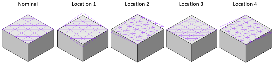
An isometric view of a planar surface with a Perpendicularity GD&T.
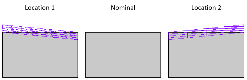
A side view of the same planar surface with a Perpendicularity GD&T.
A planar surface or axial feature (such as a hole or pin) will work with a ![]() Perpendicularity GD&T. Note: for axial features a direction is required in the Options tab. See GD&T Custom Direction for more information.
Perpendicularity GD&T. Note: for axial features a direction is required in the Options tab. See GD&T Custom Direction for more information.
A curved surface or spherical feature will not work with a ![]() Perpendicularity GD&T.
Perpendicularity GD&T.
How this GD&T Varies the Feature - Diametrical Zone:
When applying a ![]() Perpendicularity GD&T to an axial feature, a diametrical zone can be used as the zone shape. As mentioned above, the
Perpendicularity GD&T to an axial feature, a diametrical zone can be used as the zone shape. As mentioned above, the ![]() Perpendicularity GD&T will vary the orientation of the feature selected. The way 3DCS varies orientation on an axial feature is to orient the feature about the Feature Locator Point (located axially central, at v = 0.5 on the feature) such that there is no location variation at the Feature Locator Point and maximum location variation at the ends of the pin or hole.
Perpendicularity GD&T will vary the orientation of the feature selected. The way 3DCS varies orientation on an axial feature is to orient the feature about the Feature Locator Point (located axially central, at v = 0.5 on the feature) such that there is no location variation at the Feature Locator Point and maximum location variation at the ends of the pin or hole.
A sample feature with how a ![]() Perpendicularity GD&T would commonly deviate it is shown below.
Perpendicularity GD&T would commonly deviate it is shown below.
Note: While only a few deviated locations are shown below, the actual variations will use the entire specified zone.
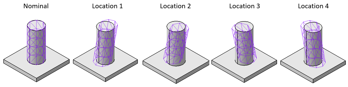
An isometric view of a pin with a Perpendicularity GD&T.
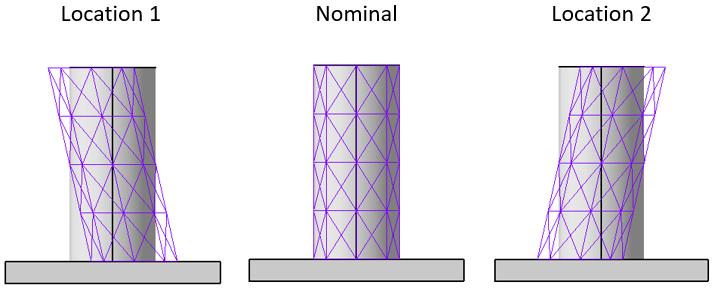
A side view of the same pin with a Perpendicularity GD&T.
Special Case - DRF Only Allows One Rotational Variation:
As shown in the images above, typically the variation applied for a ![]() Perpendicularity GD&T on a planar surface will vary the plane within a 3D zone meaning the feature will vary in two rotational direction. However, in the example shown below the DRF of A can only be measured back to for a check of one rotational degree of freedom. If this is the case, then 3DCS only will vary the planar surface in the allowable rotational direction.
Perpendicularity GD&T on a planar surface will vary the plane within a 3D zone meaning the feature will vary in two rotational direction. However, in the example shown below the DRF of A can only be measured back to for a check of one rotational degree of freedom. If this is the case, then 3DCS only will vary the planar surface in the allowable rotational direction.
A sample feature with how a ![]() Perpendicularity GD&T would deviate it in this special case is shown below.
Perpendicularity GD&T would deviate it in this special case is shown below.
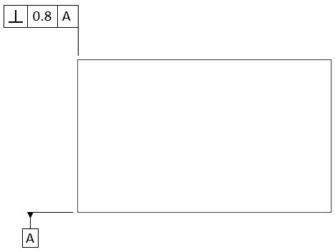
This Perpendicularity GD&T only references Datum A so that means the angle can only be measured back to Datum A.
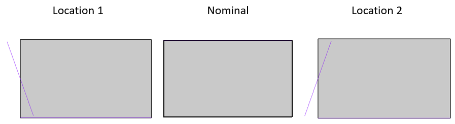
A side view of the special case deviation for the above Perpendicularity GD&T.
Applying Maximum Material Condition (MMC) or Least Material Condition (LMC) for Bonus:
Material Modifiers are allowed for a ![]() Perpendicularity GD&T for a feature that also has a
Perpendicularity GD&T for a feature that also has a ![]() Size GD&T. 3DCS will give an error if
Size GD&T. 3DCS will give an error if ![]() for MMC, or
for MMC, or ![]() for LMC are present in the Material Modifiers drop-down for a feature that does not also have size variation. For more information on Bonus Tolerance see Bonus Tolerance.
for LMC are present in the Material Modifiers drop-down for a feature that does not also have size variation. For more information on Bonus Tolerance see Bonus Tolerance.
Perpendicularity as a Refinement:
It is common for ![]() Perpendicularity to be a refinement of a location GD&T such as
Perpendicularity to be a refinement of a location GD&T such as ![]() Surface Profile or
Surface Profile or ![]() Position such as what is seen in the image below. If this is the case then 3DCS by default uses an RSS methodology to take the refinement into account without exceeding the limits of the location boundary. Settings for this can be changed depending on GD&T deviation method or Distribution input. See RSS Method for more information. An example callout for this is shown below.
Position such as what is seen in the image below. If this is the case then 3DCS by default uses an RSS methodology to take the refinement into account without exceeding the limits of the location boundary. Settings for this can be changed depending on GD&T deviation method or Distribution input. See RSS Method for more information. An example callout for this is shown below.
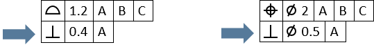
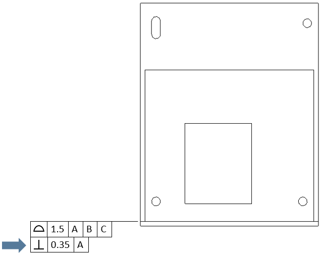
Examples of callouts where Perpendicularity is a refinement of a Surface Profile GD&T and Position GD&T.
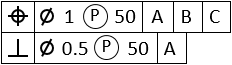
Adding a Projected Tolerance Zone:
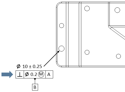
On the drawing there may be a Projected Tolerance Zone that is associated with the ![]() Perpendicularity GD&T like the one shown on the note below. If this is the case then the user can set the Projected Tolerance Zone length in the Projected Tolerance Zone field of the Options tab. By default the Projected Tolerance Zone is 0 which means it is off. The default direction of the Projected Tolerance Zone is based on the feature direction assigned by 3DCS to the hole selected. This direction is often an arbitrary direction, so if the Projected Tolerance Zone should be applied in the opposite direction of the 3DCS assigned direction, the user can simply activate the Switch Project Direction checkbox to flip the direction used for the Projected Tolerance Zone.
Perpendicularity GD&T like the one shown on the note below. If this is the case then the user can set the Projected Tolerance Zone length in the Projected Tolerance Zone field of the Options tab. By default the Projected Tolerance Zone is 0 which means it is off. The default direction of the Projected Tolerance Zone is based on the feature direction assigned by 3DCS to the hole selected. This direction is often an arbitrary direction, so if the Projected Tolerance Zone should be applied in the opposite direction of the 3DCS assigned direction, the user can simply activate the Switch Project Direction checkbox to flip the direction used for the Projected Tolerance Zone.
 .
.
This is an example of a callout that has a Projected Tolerance Zone. In this case, the zone is of length 50 so that is what would be entered into the Options tab.
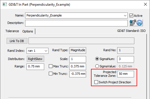
This is where a Projected Tolerance Zone can be added to the Options tab of the GD&T dialog.