The Options tab of the GD&T dialog holds more parameters to set for a specific GD&T.
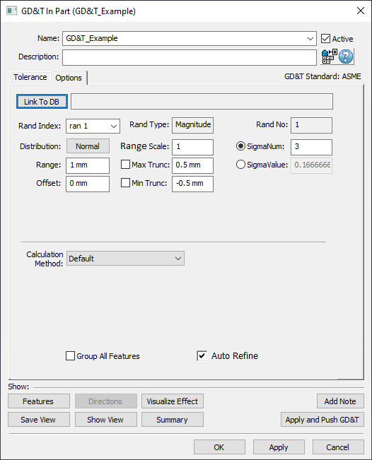
Link to DB: will link the tolerance to the Process Capability Database. This function will display a link to the Process Capability Database, if available. The user will need to create a Database first and then set a tolerance to be used in the GD&T dialog.
When using GD&T in 3DCS, |
Distribution: Allows the user to specify the type of distribution for the GD&T Range. See Distributions for more information.
Range / Offset: These values associated with the tolerance are entered into their appropriate text boxes and will be populated based on the inputs from the Tolerance tab. Users can change how these are displayed in the Preferences dialog under MTM Defaults. The Offset setting will be hidden for diametrical zones, orientation tolerances, and form tolerances, as well as for ran 2 if the frame is made composite.(Range = MaxSample - MinSample), (Offset = (MaxSample + MinSample) / 2)
Rand Index: GD&T in 3DCS have one or two random numbers, depending on whether or not the GD&T is composite or not.
•Ran#1 represents GD&T Range
•Ran#2 (where applicable) represents the FRTZF Range for a Composite GD&T.
Range Scale: Applies a multiplication scalar to the Range. Commonly used when the Range is very small and requires amplification to be seen during Deviation. For RSS, the scale will be first applied to the range and then, 3DCS will RSS while running the simulation.
Min/Max Truncation: Allows the user to set the minimum/maximum value of the GD&T. See Truncation for more information.
SigmaNum: Specifies how many ± standard deviations the distribution of samples will be between the GD&T limits. (SigmaNum = (MaxSample - MinSample) / 6), Commonly used to specify a Cp value (when there is no Offset, Cp = SigmaNum / 3). SigmaValue will automatically update based on the Range and SigmaNum used. Not available for all distribution types.
SigmaValue: Specifies the value of the standard deviation for the distribution. SigmaNum will automatically update based on the Range and SigmaValue used. Not available for all distribution types.
Projected Tolerance Zone: Allows user to set the Projected Tolerance Zone value. The default value of zero means there is not a Projected Tolerance Zone for this GD&T. By default the direction of the Projected Tolerance Zone is along the Feature's direction. Not available for all GD&T types.
Switch Project Direction: If the Projected Tolerance Zone should be in the opposite direction of the Feature's direction, then this checkbox can be activated to flip the zone direction. Not available for all GD&T types.
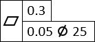
Unit Basis: Often called Rate of Change, Unit Basis controls the amount of variation within a certain distance. It is usually a refinement of a form range. The form range will define the total amount of variation. The rate of change determines the allowed relative variation at a relative location within a set distance. Typically on a drawing a Unit Basis callout looks something like the image below (could be other form tolerance types). Not available for all GD&T types. See Unit Basis for more information.
Calculation Method: Allows the user can specify the calculation method to build the GD&T internal DRF frame: Ls LCS, Ls HP LCS, Nominal HP LCS, or Default. The Default option will follow whatever setting is chosen in the Preferences dialog. See Calculation Method for more information. Not available for all GD&T types.
Envelope On: Sets the Envelope Rule for a cylinder or two planar features as on or off. This setting is default as active for ASME Standard. Only available for ![]() Size type GD&T.
Size type GD&T.
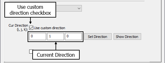
Custom Direction: If a ![]() Position GD&T is used with an empty zone shape, a direction may be required in the Options tab. The direction can either be typed in an i, j, and k value or by using the [Set Direction] option to set the direction using a different method within 3DCS. (See Vector Direction)
Position GD&T is used with an empty zone shape, a direction may be required in the Options tab. The direction can either be typed in an i, j, and k value or by using the [Set Direction] option to set the direction using a different method within 3DCS. (See Vector Direction)
Group All Features: This function deviates all features in the Features list of the Tolerance tab by the same value on each build. Not available for all GD&T types.
Feature Clocking: Only applies to Composite Position GD&T. See Composite GD&T for more information.
Auto Refine: This option will automatically applies Orientation and Form refinements to any Location GD&T without accompanying refinement manually created. Auto Refine will be turned On by default. The Percentage amount of zone variation for Orientation and Form will be controlled in the Preference setting.
•Auto Refine will be blocked if Points are added to the feature list.
•Auto Refine can be added to only Position and Profile GD&T. Auto Refine is not applicable for Surface profile set to "No DRF".
•The Sensitivity results shows the contributor values individually for Location, Orientation and Form for the same contributor. Below is an example.

If any refinement tolerance is manually applied to the Position or Profile tolerance, Auto Refinement option will be overwritten to use the manual GD&T. |