All tolerances have a lot of parameters in common. Outlined below are the common parameters that need to be defined for all the tolerances. Parameters which are specific to the individual tolerance are specified on its help page. The following example is for a Linear Tolerance.
|
Tolerance Parameters:
Tolerance Name:
A name is required for all tolerances. 3DCS provides a default name starting with Tole1, Tole2, etc., however it is a good idea to have a unique name for each tolerance in the model. This field has been enhanced to display long part names in version 6.2.0.
Active tolerance option: When a check is present, 3DCS will perform the tolerance on the specified points.
Description: A tolerance description is recommended but not required. The description helps users describe the tolerance in their own words.
Help: The Help button is context sensitive; it will open the Help Manual at required tolerance page.
Mode: The Mode describes how the features will be tolerance with respect to each other.
Features: This list box lists all the points and Features that carry this tolerance. Their respective part names are next to them in parenthesis.
•The Add and Delete buttons enable selection or deletion of points.
oThe Add button allows the user to select individual points with the cursor from the graph window as well as select multiple points by dragging a window with the mouse around the desired points. To drag a window, simply click the left mouse button at one corner of the window and hold the button down while moving the mouse to the other corner. A rectangular frame resembling a window will be made by the cursor. When the dragged window is the correct size and shape, release the button and all points within the dragged window will be selected.
oThe Delete button allows points to be deleted from the point list. To delete a point from the list, highlight the point and click on the Delete button.
•The Key In field next to the Add Win. button allows the user to highlight a point in the point list by typing the point's name in the field and pressing the Enter key. The menu will only locate points within the same part which the tolerance is located, in or any sub part under it.
Directions: Refer to the specific tolerance type for individual tolerance direction definition.
The drop-down list next to Dir. Type has five choices for defining the tolerance direction: Type In, Two Pt, Normal, AssocDir and PickPtDir.
Dir. Index: lists all available directions.
Dir. Number: shows how many directions have been selected.
Multiple Directions: when checked, this allows for each point to have an associated direction, without affecting the other points/features listed in the tolerance box.
•Users can select either a Feature in the list to change the direction; or switch the Direction list box to the desired direction number. For example: If six features are listed, six directions will be listed.
•Multiple Directions is recommended when using a combination of direction types (Type In, Two Pt, Normal, Assoc, TwoPtDir). If all points have AssocDir, Multiple Directions is not necessary.
•Turning off Multiple Directions will prompt the next message: "All directions will be lost. The currently displayed direction will apply to each point".
See: Vector Direction for more information about each available direction.
Link to DB: This function will link the tolerance to the Process Capability Database.
Deviations - Random number index:
The Rand Index pull-down menu allows the user to switch between the different types of deviations for the tolerance. See the individual type of tolerance for more information.
3DCS Tolerances |
Rand #1 |
Rand #2 |
Rand #3 |
Rand #4 |
Linear |
Magnitude |
Magnitude - If Composite is selected |
N/A |
|
Circular |
Radial Magnitude |
Angle |
Radial Magnitude - If Composite is selected |
Angle - If Composite is selected |
Arc |
Radial Magnitude |
Angle |
N/A |
|
User-DLL |
Any, Unlimited |
N/A |
||
Dual |
Magnitude |
Magnitude |
N/A |
|
Triple |
Magnitude |
Magnitude |
Magnitude |
N/A |
Radial Profile |
Magnitude |
N/A |
||
Magnitude Definition: The magnitude defines the range of the tolerance and other parameters associated with it.
Angle Definition: If an angle tolerance is activated, perform the above instructions in this section also. (Arc Tolerance, Circular Tolerance)
Range: The tolerance value. (Range = MaxSample - MinSample). The Range and Offset display can be changed to show Plus/Minus, "+/- and Offset", Upper/Lower, or Range/Offset in the 3DCS Preferences, under Model Settings.
Offset: If the offset is zero, the tolerance range is split equally. For ex., if the range is 6 and offset is 1 then the tolerance field will be from -2 to +4. If the Offset equals zero, the tolerance is -3 to +3. (Offset = (MaxSample + MinSample) / 2). Offset will not be available for 2D Normal, Uniform Triangle and Trapezoid distributions.
Distribution: The type of distribution that describes the tolerance region. Click the button under Distribution and select the type of distribution you would like, then click OK or Close button.
Min Truncation: The minimum value of the tolerance. See Truncation
Max Truncation: The maximum value of the tolerance. See Truncation
Sigma Number (=3*Cp): Specifies how many ± standard deviations the distribution of samples will be between the tolerance limits. (SigmaNum = (MaxSample - MinSample) / 6)
Sigma Value (also called Standard Deviation): a quantity calculated to indicate the extent of deviation for a group as a whole.
Angle HLM Level: Angle HLM applies to the tolerance angle similar to the HLM Level.
Range Scale: The scale field is used to specify a multiplication factor for the tolerance. For instance if the user specifies 2, the tolerance is multiplied by a factor of 2. For RSS, the scale will be first applied to the range and then it will do RSS while running the simulation.
Multi-Scale - specific to Linear and Circular tolerances: Allows the user to select a different scale for each point selected in the tolerance.
•Multiple features or points will be required to use this option.
•Warning: When using multiple scale factors, switching the Mode between Independent, Grouped or Composite will cause all multiple scale values to be reset to 1. A warning message appears for this.
Other Information:
Show: Highlights the Points or Features used in the tolerance in the Graph window. Likewise, the Direction button allows the user to view the direction of all the points in the tolerance point list.
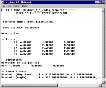
Clicking on the Summary button will open a Notepad file that contains the Tolerance dialog box input.
Add Note: Add text or images that will be included in the report.
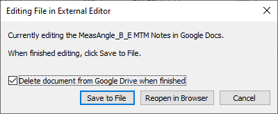
•If using Google Docs, edit the notes, return to 3DCS and select [Save to File] button.
oDelete document from Google Drive when finished - removes the Doc from the user's Google Drive.
Notes:
•When creating a new Note or Editing a Note within any MTM or GD&T dialog, Word will open. Once the user closes Word or the External Editor dialog, the HTML will be saved in the correct format and saved with the model. Users can Close Microsoft Word with the Notes and Images, but will need to select Yes and Yes: first to save the Note and Image to the dcstemp.htm and Yes to save the correct HTML format.
Closing the dialog:
Clicking on OK accepts all the parameters entered and takes you to the list tolerances dialog box where tolerances are created, edited or deleted.
Clicking on Cancel quits the dialog box to the previous level without accepting any parameters.