All the setting in this Tab will be saved along with the model.
Within this section: |
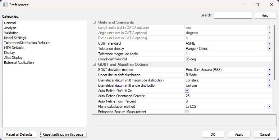
Length Unit: Set the units with a number of different choices including mm, cm, in, ft, etc. 3DCS Length units is controlled by the CAD Units, user need to change the CAD Length units to see the change in 3DCS Length Units.
Angle Unit: Set the units from degrees to radians.3DCS Angle units is controlled by the CAD Units, user need to change the CAD Angle units to see the change in 3DCS Angle Units.
Force Unit: Set the units of different choices including N, mN, Ibf, kgf.3DCS Force units is controlled by the CAD Units, user need to change the CAD Angle units to see the change in 3DCS Force Units.
3DCS will show the results in Volume (^3) and Area (^2). If no unit is set, the results will only show the values. These units will also be shown in the measure dialog: Current and Upper Spec Limit/Lower Spec Limit fields. |
GD&T Standard: Set the GD&T standard to either ASME (default), ISO or JIS to be used in the analysis. This setting is saved along with the Model.
Tolerance display: Displays the input method of the tolerance to be either Range and Offset, Plus and Minus, Plus, Minus and Offset, and Upper and Lower.
Tolerance Magnitude Scale: The Tolerance Magnitude Scale allows the user to scale all the tolerances in a model.
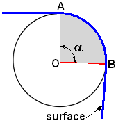
Represents the surface curvature, measured by angle a, and controls whether or not a cylinder or surface of revolution is treated as 3DCS hole/pin center point. The default value for the angle is 95 degrees. If the value for this angle becomes larger than the set number for Cylinder Threshold, the surface will be treated as a cylinder.
For example, this function allows the user to find the center of a cylinder, when the cylinder is designed with multiple faces: Face_1, Face_2, Face_3.
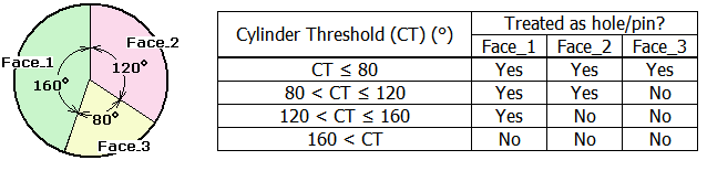
Cylinder Threshold setting applies per model, not per individual surfaces. It is saved as a setting when saving the model, and takes effect when the geometry is being updated. |
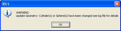
Modifying the cylinder threshold can result in a surface changing from cylinder to non cylinder or vice-versa, due to the angle of the surface is either within or not within the threshold. The points location will not change, but the value of the U-V coordinates on the surface will be modified, and the center points will loose their associated circle. By restoring the Cylinder Threshold value to its original value, the circle will be restored. A warning appears when updating part's geometry, after Cylinder Threshold value was modified:
To apply a new cylinder threshold use Update Geometry and then Update Model if necessary.
To change the feature type from surface to cylinder reduce the Cylinder Threshold value in Preferences.
This setting is saved along with the Model.
GD&T deviation Method: 3DCS can use two different methods to calculate the GD&T: Root Sum Square (RSS) and Range Control.
Both methods deviate multiple call-outs applied to the same features in this order: Form, Orientation, and Location where Form has the full range.
Range Control uses automatic truncation of tolerances based on GD&T values. We do not recommend running analysis with this setting. Best used for Worst Case Analysis. The Statistics could be highly “skewed”; min-max values should be used.
GD&T RSS (Root-Square Sum) Method uses RSS calculated ranges. Statistics are within the intended 6-sigma ranges; min-max values may be over the intended range.
Datum Shift On: For each GD&T call-out, if the DRF contains datums with MMB modifiers, then the call-out will apply extra variation. The extra variation will be applied with the same internal feature move that aligns the varied features relative to the DRF. The datum features will float on virtual gauge pins (or in virtual gauge holes) using the distributions set below. The size of the virtual gauge pin will be determined by the size of the datum feature and the call-outs applied to it. Unlike the Feature move, the size of the datum feature used in the float calculations will be based on its full mesh.
Linear Datum Shift distribution: Sets the distribution type used with a 2-way datum (e.g. a slot held by a round pin.
Diametrical Datum Shift distribution: Sets the distribution type used with a 4-way datum (e.g. a round hole held by a round pin.) See also: Datum Shift
Auto Refine Default On: Will control the Active/Inactive status of Auto Refine in newly created GD&T.
Auto Refine Orientation percent: Automatically applies an Orientation refinement to the Geometric Tolerance. The option in the GD&T dialog would need to be active to apply the refinement to the Contributor. Default 25% of Location.
Auto Refine Form percent: Automatically applies a Form refinement to the Geometric Tolerance. The option in the GD&T dialog would need to be active to apply the refinement to the Contributor. Default is set to 0% Form.
Plane Calculation Method: Select the calculation method to calculate the feature location for the GD&T and the Feature Move.
•Least Squares Local Coordinate System
•Default - Default Feature Move and GD&T setting. If the Plane Calculation changed in the Preferences, all Feature Moves and GD&T set with Model Setting will use the Preferences setting. Each Feature Move and GD&T can independently be set to a different Calculation Method.
Enhanced Feature Measurement: This activates the mechanical modeler license to use the new Enhanced Feature Measurement calculation routine. Turning it off will use the old feature measure calculation.
Enhanced Feature Measurement (Exact Mode): Uses more precise interference calculation for the Feature and Part Distance Measure. This setting will slow down Nominal Build and the Analysis process for models with Feature Measures.
No Build Upon Failure in Iterative Move: will set the default active or inactive for the "No Build Upon Failure" check box.
Model report directory: This option allows the user to save 3DCS generated files to a specific folder, such as when running a new Simulation (HST/HLM), or Generating Reports. This option controls the location of Analysis files: Batch and Script files, Analysis Results (Monte Carlo, GeoFactor and Contributor Analysis) files.
Default Location: 3DCS sets the default location for the Analysis results and Reports to: C:\Users\<username>\Documents\DCS\DCS_V5
Assembly/Model Location: In the same directory as the top level 3DCS Model.
User Specified Location: Any directory the user chooses. This setting will be saved per model.