This section allows the user to set the default Tolerance Distributions, Range, Offset, Min/Max Truncation, and Sigma number to be set for the Axial and Surface Location, Orientation, Form and Angular Tolerances.
|
Min/Max Truncation
The Min and Max Truncation can activate/deactivate on tolerance creation and based on the Truncation range. This option will apply to all Tolerances and GD&T.
Example: A Linear tolerance with a range of 2 and a Min/Max Truncation range of 0.4 (+0.2,-0.2), the Analysis results will only show a curve between the range of 0.4.
![]() Surface Location (Profile, Position)
Surface Location (Profile, Position)
Surface location Distribution:Sets the default distribution type for Profile and Position (non-diametrical zone, ISO Standard). Once a Tolerance or GD&T is created, each new GD&T or Tolerance will have their default Distribution applied. Surface location Range: Sets the Range value for all GD&T and 3DCS Tolerances. Surface location Offset: Sets the Offset value for all new GD&T and 3DCS tolerances. Surface location Min/Max Truncation: Add a Min/Max Truncation value and active/deactivate the Min or Max Truncation to be used. Truncation will trim the tolerance range value output within the Truncation values. Surface location Sigma Number: Apply a Sigma Number value when a new Profile or Position (non-diametrical zone) GD&T is created. |
|---|
![]() Surface Orientation (Perpendicularity, Angularity)
Surface Orientation (Perpendicularity, Angularity)
Surface orientation Distribution: Sets the default distribution type for Perpendicularity (non-diametrical zone) and Angularity. Once a Tolerance or GD&T is created, each new GD&T or Tolerance will have their default Distribution applied. Surface orientation Range: Sets the default Range value for all GD&T and 3DCS Tolerances. The range can also be set to show Range/Offset, Plus/Minus,+/- and Offset. Surface orientation Offset: Similar with setting the Range value, this option sets the default Offset value to all GD&T and 3DCS Tolerances. Surface orientation Min/Max Truncation: Add a Min/Max Truncation value and active/deactivate the Min or Max Truncation to be used. Truncation will trim the tolerance range value output within the Truncation values. Surface orientation Sigma Number: Apply a Sigma Number value when a new Profile or Position (non-diametrical zone) GD&T is created. |
|---|
![]() Surface Form (Flatness, Profile (No DRF), Linear Tolerance)
Surface Form (Flatness, Profile (No DRF), Linear Tolerance)
Surface Form Distribution: Sets the default distribution type for Flatness, Profile (No DRF) or Linear Tolerance (Independent mode). Once a Tolerance or GD&T is created, each new GD&T or Tolerance will have their default Distribution applied. Surface Form Range: Sets the default Range value for all GD&T and 3DCS Tolerances. The range can also be set to show Range/Offset, Plus/Minus,+/- and Offset. Surface Form Offset: Similar with setting the Range value, this option sets the default Offset value to all GD&T and 3DCS Tolerances. Surface Form Min/Max Truncation: Add a Min/Max Truncation value and active/deactivate the Min or Max Truncation to be used. Truncation will trim the tolerance range value output within the Truncation values. Surface Form Sigma Number: Apply a Sigma Number value when a new Profile or Position (non-diametrical zone) GD&T is created. Material Modifier: Applies the MMC (M), LMC (L) or None (RFS) to the Flatness (GD&T) when creating a Flatness tolerance. |
|---|
![]() Axial Location (Position, Circular Tolerance)
Axial Location (Position, Circular Tolerance)
Axial Location Distribution: Sets the default distribution type for Position and Circular Tolerance. Once a Tolerance or GD&T is created, each new GD&T or Tolerance will have their default Distribution applied. Axial Location Range: Sets the default Range value for all GD&T and 3DCS Tolerances. The range can also be set to show Range/Offset, Plus/Minus,+/- and Offset. Axial Location Offset: Similar with setting the Range value, this option sets the default Offset value to all GD&T and 3DCS Tolerances. (Only applied to Circular Tolerance; Position tolerance ignores this setting). Axial Location Min/Max Truncation: Add a Min/Max Truncation value and active/deactivate the Min or Max Truncation to be used. Truncation will trim the tolerance range value output within the Truncation values. Axial Location Sigma Number: Apply a Sigma Number value when a new Profile or Position (non-diametrical zone) GD&T is created. Material Modifier: Applies the MMC (M), LMC (L) or None (RFS) to the Position (GD&T) and Circular Tolerance, when creating a Position and Circular tolerance. |
|---|
![]() Axial Orientation (Perpendicularity, Angularity)
Axial Orientation (Perpendicularity, Angularity)
Axial Orientation Distribution: Sets the default distribution type for Perpendicularity and Angularity. Once a Tolerance or GD&T is created, each new Position, Profile, Linear Tolerance, etc., will have their default Distribution applied. Axial Orientation Range: Sets the default Range value for all GD&T and 3DCS Tolerances. The range can also be set to show Range/Offset, Plus/Minus,+/- and Offset. Axial Orientation Offset: Similar with setting the Range value, this option sets the default Offset value to all GD&T and 3DCS Tolerances. (Only applied to Circular Tolerance; Position tolerance ignores this setting). Axial Orientation Min/Max Truncation: Add a Min/Max Truncation value and active/deactivate the Min or Max Truncation to be used. Truncation will trim the tolerance range value output within the Truncation values. Axial Orientation Sigma Number: Apply a Sigma Number value when a new Profile or Position (non-diametrical zone) GD&T is created. Material Modifier: Applies the MMC (M), LMC (L) or None (RFS) to the Perpendicularity (GD&T), when creating a Perpendicularity tolerance. |
|---|
Axial Form Distribution: Sets the default distribution type for Straightness. Once a Tolerance or GD&T is created, each new GD&T or Tolerance will have their default Distribution applied. Axial Form Range: Sets the default Range value for all GD&T and 3DCS Tolerances. The range can also be set to show Range/Offset, Plus/Minus,+/- and Offset. Axial Form Offset: Similar with setting the Range value, this option sets the default Offset value to all GD&T and 3DCS Tolerances. (Only applied to Circular Tolerance; Position tolerance ignores this setting). Axial Form Min/Max Truncation: Add a Min/Max Truncation value and active/deactivate the Min or Max Truncation to be used. Truncation will trim the tolerance range value output within the Truncation values. Axial Form Sigma Number: Apply a Sigma Number value when a new Profile or Position (non-diametrical zone) GD&T is created. Material Modifier: Applies the MMC (M), LMC (L) or None (RFS) to the Perpendicularity (GD&T), when creating a Perpendicularity tolerance. |
|---|
![]() Angle for Circular Tolerance (Rand#2)
Angle for Circular Tolerance (Rand#2)
Angle for the Circular Tolerance refers to the Random #2 in the Rand# list. By switching to Rand#2, the user can set the default settings for the Angle in the Circular Tolerance. To set the Rand#1 settings, look to setting the Axial Location settings.
Angle Distribution: Sets the default distribution type for Straightness. Once a Tolerance or GD&T is created, each new GD&T or Tolerance will have their default Distribution applied. Angle Range: Sets the default Range value for all GD&T and 3DCS Tolerances. The range can also be set to show Range/Offset, Plus/Minus,+/- and Offset. Angle Offset: Similar with setting the Range value, this option sets the default Offset value to all GD&T and 3DCS Tolerances. (Only applied to Circular Tolerance; Position tolerance ignores this setting). Angle Min/Max Truncation: Add a Min/Max Truncation value and active/deactivate the Min or Max Truncation to be used. Truncation will trim the tolerance range value output within the Truncation values. Angle Sigma Number: Apply a Sigma Number value when a new Profile or Position (non-diametrical zone) GD&T is created. |
|---|
![]() Angle Size Tolerance (Angle Size, Arc Tolerance)
Angle Size Tolerance (Angle Size, Arc Tolerance)
Angle Size Distribution: Sets the default distribution type for Straightness. Once a Tolerance or GD&T is created, each new GD&T or Tolerance will have their default Distribution applied. Angle Size Range: Sets the default Range value for all GD&T and 3DCS Tolerances. The range can also be set to show Range/Offset, Plus/Minus,+/- and Offset. Angle Size Offset: Similar with setting the Range value, this option sets the default Offset value to all GD&T and 3DCS Tolerances. (Only applied to Circular Tolerance; Position tolerance ignores this setting). Angle Size Min/Max Truncation: Add a Min/Max Truncation value and active/deactivate the Min or Max Truncation to be used. Truncation will trim the tolerance range value output within the Truncation values. Angle Size Sigma Number: Apply a Sigma Number value when a new Profile or Position (non-diametrical zone) GD&T is created. |
|---|
![]() Size Tolerance (Size Tolerance, Circle Tolerance)
Size Tolerance (Size Tolerance, Circle Tolerance)
Size Distribution: Sets the default distribution type for Straightness. Once a Tolerance or GD&T is created, each new GD&T or Tolerance will have their default Distribution applied. Size Range: Sets the default Range value for all GD&T and 3DCS Tolerances. The range can also be set to show Range/Offset, Plus/Minus,+/- and Offset. Size Offset: Similar with setting the Range value, this option sets the default Offset value to all GD&T and 3DCS Tolerances. (Only applied to Circular Tolerance; Position tolerance ignores this setting). Size Min/Max Truncation: Add a Min/Max Truncation value and active/deactivate the Min or Max Truncation to be used. Truncation will trim the tolerance range value output within the Truncation values. Size Sigma Number: Apply a Sigma Number value when a new Profile or Position (non-diametrical zone) GD&T is created. |
|---|
Here is a list of the available default Distribution values used in the 3DCS Preferences. Please check the Distributions page to find more information about each Distribution.
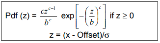
Weibul4 parameters: This is a generic distribution, controlled by four parameters: Offset, Sigma (σ), Scale (b), and Shape (c). The Offset and Sigma parameters are set on the Edit Feature Tolerance dialog
•Weibul4 Scale: Default = 1 •Weibul4 Shape: Default = 3 Pearson4 parameters: This is a generic distribution, controlled by four parameters: Offset, Sigma, Skewness, Kurtosis. The Offset and Sigma parameters are set on the Edit Feature Tolerance dialog. •Pearson4 Skewness: Default = 1 •Pearson4 Kurtosis: Default = 3 Trapezoid Left/Right: This distribution creates a trapezoid-shaped curve. Two Extra Parameters are needed for this distribution. They control the percent of the total range that will be in each triangular portion of the distribution. •Left parameter represents the length of the "growing" section, and Right parameter represent the length of the "decaying" section, for a standard distribution with a range of one. These parameters should vary within [0, 0.5] interval. The b, c, and h values for the user distribution will be calculated based on the Left (Db), Right (Dc), min and max values. •Trapezoid Left = 0.25 •Trapezoid Right = 0.25 Power Function Shape: The Power Function Distribution (PFD) is a flexible distribution as it is able to model the various types of data. It is usually used for the reliability analysis, life time and income distribution data. Default shape value = 0.5. |
|---|